If you are familiar with me from reading my other pages on this site, you know that I am a fanatic, not just a fan, about the Magnavox tube amplifier. Most tube audiophiles probably wouldn't even consider Magnavox, now just a manufacturer of television, and now owned by Phillips, to be a manufacturer of high quality amplifiers. Perhaps not. However, at the beginning of the tube and radio era all they did was manufacture audio equipment. Up until the sixties, it was the big three, RCA, Zenith and Magnavox (OK, Sylvania ad Emerson and others too. But they were mostly TV and Radio. Fisher, Scott, et al started in the fifties) that made the high quality equipment. They invented the dynamic speaker. They were called "The Magnificent Magnavox" by the early sixties, a title, if memory serves, they earned, not self appointed.
In spite of the fact that the old console that my father bought for $950 in 1961, about $8,000 by today's standards, was the sound that I grew up with, I prefer a true, neutral, live sound. When I became aware of sound quality and music, as a teen beginning to buy LP's, this system was all that we had for me to play my records on. The sound was very good. However, it wasn't until I decided to rebuild it, because I was slowly inheriting it as my own, that I started to notice its unique and highly accurate sound quality. I started with the obviously easy. I replaced the tubes. I was impressed with the immediate difference that the new tubes made (hence marking the beginning of my audiophile hobby, as opposed to electronics, which started six years earlier). However, one of the output tubes started to glow cherry red. I therefore needed to replace the capacitors. This cleaned up the sound a little bit more. I got nice highs and clearer mids.
It wasn't until I got my hands on some Sams Photofacts that I really started to get results. I decided to go all out with this amp. I got tube sockets, stranded 20 gauge and 18 gauge hookup wire, and 5% resistors. I believe that it was the resistors that made the biggest difference (I had done the wire previously) because when I played the system after replacing them, my father ran out of his room exclaiming "What did you do!? It hasn't sounded like that since it was new!"
Not that I was ungrateful, but I did not like the sound of it at first. The bass went from being muddy, which I liked at the time, to becoming stiff and deep. The midrange went from being fat and warm, to being not as fat and accurate. The highs went to from being sibilant to being airy and clean. The imaging went from being 10 feet wide to surrounding me from 8 feet away. After a couple of days of listening to this "new" amp, I got to the point where nothing else I heard had quite the same quality. I mean, I have heard studio quality equipment and high end stuff, and NONE of them sounded as good.
This became especially disheartening when the amp died due to an experiment gone awry. I tried to put silicon diodes in place of the 5U4 rectifier. I must have put them in wrong, or the power transformer must have been weak, because when I did this not only did it not work, but when I put the 5U4 back in, I got a low level hum that wouldn't go away no matter what I did. I must have put them in backwards. To me that marked the end of an era. At the time the replacement transformer was over $150. Considering the times (1981) it was a hefty price to pay.
So, my father got a wall unit to replace the area where the old console used to live, and a solid state stereo system. YUCK!!! was all I could say when I played my LP's. For about a year I had to live with this incredibly awful sound. Until I discovered FET's, that is. But this is now getting into another story.
THE RESURRECTION OF AN OLD FRIEND
Up until two years ago, I had been satisfied with the solid state equipment that I designed and built. It wasn't until I found a place that had a couple of tube amplifiers that I got back into playing with tube amps. I picked up an EICO 2536 integrated tube amp/FM stereo. It used 6BQ5's and 12DW7's. It used 6EU7's for the phono section. It is an 18 watt per channel push pull amp that has 8 and 16 ohm taps. Cool, I thought. I could play with it and see how my solid state amp compares to it. It used the 12DW7's, a hi mu/low mu twin triode, as a voltage amplifier/cathodyne phase splitter. Well, except for a slightly fatter midrange it sounded very much the same. I was kind of proud of myself.
I then found some circuits on the 'net that employed a similar circuit to that old Maggie (as I affectionately call it). So I decided that one day I will build it that way. The circuit was called a paraphase. It takes the output of the first triode, and either attenuates it or not, depending on whether one used a fixed gain amp or an anode follower (unity gain), and inverts the signal through this second triode to feed the bottom half of a push pull-output. Both used NFB at the inverter triode to keep it amplifying at a fixed level. The first triode's amplification was fixed by the global NFB. I bought sockets and new tubes from Triode Electronics, and a bunch of 5% resistors from Radio Shack, and some NTE capacitors. The sound was astonishingly good. Better than the cathodyne. So I was kind of settled with this as my final amplifier.
THE LETTER
Until, that is, I got a letter. It
was from a fellow Magnavox fiend named Jon Staebler. In it was the four
pages of Sams Photofacts that was the chassis of that old Magnavox tube
amplifier. I was tickled. I looked it over. It was wierd in places. I could
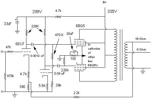
not understand why they did a couple of things. Here is the schematic (of
one channel):
Well, this is one channel. I made a couple of changes. First is the 4.7K resistor providing the B+ to the 6EU7. It is originally 10K and the filter is 10 microfarad, not the 33 µF I put in. Then the power supply uses 5 Henries where the original calls for 1. The second capacitor in the pi filter is 200 microfarads and not 30. I get absolutely no hum. I also eliminated the balance pot using a 390 ohm resistor instead, the pot being in the feedback loop of both channels (Just imagine that 390 ohm resistor being a 750 ohm pot instead, with the wiper arm going to ground and either end going to the 4.7K resistors to the cathodes of each channel. That was a sort of balance control).
The first thing was where the NFB went. How the heck does it do its thing? Second was the two different values of capacitor to the output tubes. How the heck does the bass get through those? Then the kicker was that all four output tubes were tied together at the cathodes to one cathode resistor. What the heck??!! How does the signal remain stereo???
Well, let's analyze it.
The first stage is kind of straight forward. The cathode voltage is supposed to be 2 volts (not the 20 that the Sams mistakenly says). Actual measurement is about 1.5. The input has what is known as a stopper resistor, which minimizes high frequency oscillation. The gain of the stage is about 7.8. If one looks at the cathode circuit closely, one can imagine it as also being a common grid amplifier, where the input is the cathode, and the cathode resistor is a stopper, whereas the 390 ohm resistor is the input impedance. This allows both the input signal and the fed back signal to mix in the tube. This brings the tube's gain down to about 6 (2200/390 || 1/Gm+4700).
The output of that triode goes through a 0.0012 µF capacitor. This cap has a roll off at about 200 Hertz. This is OK, because it will all be brought back to a flat level with what is below it by NFB (more later). It feeds the top 6BQ5, which has a gain of about 25 (tube hooked as pentode should be a max of 500). So overall theoretical gain is 7.8 times 25 or 195. Ah, but we really need to include the output transformer in this because it steps down the voltage. So assuming that the output tubes go full swing at a B+ of 320 volts, we get the RMS voltage, or 320 X 0.707 to get 226 volts. Now, assuming that the output is the 18 watts that the EICO called for with this transformer, then we use the formula to get voltage from power and resistance (assuming 16 ohms impedance is equivalent to impedance), or V=SQRT(PR), or V=SQRT(18X16) =16.9. So, the 226 volts gets cut down to 16.9 volts. Which means that that stage amplifies the signal, assuming with bias set at 12.7 volts (measured) (12.7*.707 for RMS, or 8.98 volts) then from 8.98 to 16.9 volts is about 1.88. So open loop gain is actually about 7.8 times 1.88, or 14.66. This amp needs a 1 volt signal to put out full power open loop.
The output of this triode also goes through a voltage divider/grid resistor (for both the top pentode and the phase inverter triode) to the phase inverter triode. This stage has a gain of about 6.4 (theoretically). Not exactly even gain with the first triode, but with NFB close enough. This then amplified but inverted signal gets passed through a 0.047 microfarad capacitor that has a roll off at 18 hertz with the 220K grid resistor at the pentode.
So, the resultant signal then passes through the transformer with all of its distortions and brought back to the input to both attenuate the amplifier overall to a gain of 6. So for full power this amp needs 16.9/6 or 2.8 volts for full power out. Not a problem. I have a preamplifier that will provide this.
Now notice that all four output tubes are tied together at the cathodes going through one resistor? Usually, only one pair per channel shares a common cathode resistor for push pull operation. Although each output tube could use individual resistors, this would require a negative bias supply to bring the tubes close to cut off (class AB1 is where the tubes are close to cut off so at low volume levels they act as class A bias. At louder volume levels it behaves as a class B amp. Class B operation has tubes at cut off, but at low volume levels sound is distorted). Tying them together allows for easier self biasing schemes and the transition of a signal from one tube to the other. This usually requires matched pairs of tubes in order for both tubes to be biased at the same level (matched pair is where both tubes flow the same current at the same voltage level). I was fortunate to get a matched quad. I say this because all four have a common current source. Also with a pair of tubes in push pull, if there is a difference between the phase inverter and the output of the first tube (which we have here), the differential nature of the output tubes causes there to be a balance of output, because both signals add within the differential pair, so the output of each tube is equal.
Anyway, I was confused about how the signal didn't mix between the two channels. But I figured that is was the same reason that a long tailed pair did not have a signal at that point. Common currents cancel at that point. The bypass capacitor takes care of anything that leaks past. On the other hand, I am of the opinion that it also aids in the stereo separation. Anything that does leak past to the other channel would be out of phase with the first channel, so it might create an imaging effect. On the other hand, it does seem to make for a stiffer current control for each tube. If one is going positive, two of the others remain idle at a fixed current (This condition would be for one channel getting a pure sine wave). This is also an interesting way to make the amp more efficient. One gets the maximum gain for that one tube's full positive swing, because for that moment it only sees the resistor as its own cathode resistor. So it can provide its maximum power level while idling at a low power level.
As far as the imaging effect, I say this because of the similarity of another amplifier made by Steve Deckert at Decware. His single ended amplifier can also be bridged for 10 watts power. But when used as an SE amp, the two output tubes share a single cathode resistor also. He and others claim to have a surrounding effect from the amp. I get the same kind of imaging from this amp.
THE DESIGN PHILOSOPHY
Let's look closer to the frequency response of this amplifier. Many designers design the amplifier to amplify from the lowest frequency desired to the highest attainable before using NFB. However, as mentioned earlier, this amp rolls off at 200 Hertz. NFB takes over and brings this amp likely to as low as 20. How does this do it, and why did the designers of this amp decide to roll off at 200?
As it is, the open loop frequency response, as calculated by me and told to me by others, is about 200 to 10,000 hertz. Now, typically an amplifier has a roll off at either end of 6 dB per octave. So my the time the amplifier gets to the frequencies we want, they are being amplified at a much lower gain. For the high end it is an easy task to regain the high frequency of 20,000 hertz because the next octave up from 10,000 is 20,000. So we could merely feed back enough signal to reduce the gain by 6 dB. But going down from 200 Hertz takes a little more work. Halving down the octaves from 200 we have 200/2=100, 100/2=50, 50/2=25. So if we want to go down to at least 25 we need to go down 6dB times three, or 24 dB. This is not that easy. Well it is, but it requires an amplification such that when the reduction is applied, the gain is still sufficient to drive speakers.
Let's say that the amplifiers gain is 1000 (a threoretical analysis here). This represents a dB gain of 60 (every gain of 10 times is 20 dB. For example, 10 times is 20 dB, times 10 or 100 is 40dB, times 10 or 1000 is 60 dB). So to drop the gain 24 decibels requires that I drop the gain to less than 100. I guess about 92 (don't have the formulas on hand). But, the 25 hertz is still 6 dB below a flat response, so I want to reduce the gain further. So I drop the gain another 10 dB. This brings the amp down do about 20. OK, so the 20 hertz is still a little lower, than flat, but not so low. Nah, let's bring it to the same level as the rest. Let's bring it down another 6 dB. Now the gain is about 10. The level of 20 Hertz is the same as 20,000 hertz. The overall amplifier response may well be way beyond that, but roll off due to the transformer and speakers and crossover networks reduce the response anyway. But at least the amp can do it.
(Please note the above analysis is theoretical. This amp does not amplify that much. Yet it has a very deep and flat bass response. This is merely an example with arbitrary but realistic numbers)
So now I have an amplifier whose response is flat from 20-20,000 Hertz, give or take a little. Supposedly the give or take at this stage of the game will be a couple of tenths of a decibel. Good enough for the most stringent listener. Harmonic and intermodulation distortions should also be in the low tenths.
Here is the thing I think the designer was thinking regarding the open loop frequency response: Back when this amplifier was made, the acoustic suspension speaker had not really been widely available (I do not think it was even made then). Much of the hoola about getting that lifelike sound was in getting as much bass with as big a woofer as possible. However, speakers then were very stiff. So damping was not so much of an issue. This amplifier was made to not damp the bass as much as other designs. So it would be able to provide as much bass as was desired with out having to damp it down, since the speakers did not even need it, except at a hgher frequency. 200 hertz was pretty close to around the frequency that a stiff 12 inch woofer would resonate at. This is why I now get a deeep bottom end with my acoustic suspension speakers. Though I do have them damped pretty stiffly with a sealed and well insulated box.
HOW DOES THE BUGGER SOUND?
OK, here goes. First, each instrument and voice is so defined and individual that it is spooky. I have heard many very good audio systems. But this amp brings out stuff from the recordings (that is, anything from LP's with lots of pops and clicks to DVD's) that I have become intimate with, that I have heard for the first time playing it through this amp (is this redundant?). I hear noises like chair squeaks and breathing(!) and people in the background that were never there before.
Each individual instrument has a full range of tonality that goes from the fundamental to both directions of the audio spectrum. But it does not sound colored. It sounds neutral. But it does not sound sterile. It sounds extended, but it sounds absolutely flat. Quite frankly I did not know that such sound could come out of the speakers I have. Oh, they are good and I designed them to exacting tolerances, but MAN!
As an example of what I mean by the flatness, I played a direct metal mastered recording of Beethoven's 6th symphony. This is my absolute test of an amplifiers dynamic range and quality. The third movement has a part in it that is known as the thunderstorm. It starts out very soft with the violins sounding as if there were a couple of rain drops starting out, then the basses warn of thunder in the distance. The rain gets a little heavier and some more louder thunder. Then a bang of thunder occurs and the rain gets heavy and furious. Well, I got knocked out of my seat. It really startled me. I did not expect such a dynamic range from a 15-18 watt per channel amp into speakers designed for 150 watts. The sound was not strained in the least (must be the 200 microfarads of filter caps. Original circuit calls for 30!). The tympanis had equal amplitude and force. Solid state amps and push-pull tube amps tend to emphasize the lower frequency tympani, and tube SE amps and FET amps tend to emphasize the upper tympani. This one was exactly the same for the two (I think I only heard two tones). And you could actually hear the attack distinctly each time the person hit the tympani. A lot of amps I have heard tend to blend or blur this together. Also, in the right channel as the tympanis and bass are displaying their wrathful thunder, the violins on the right channel are displaying sheets of rain coming down, and one can hear the rosin drenched bow scratching across the violin string as the fingers dance their way up and down, each note coming out with equal amplitude. From the highest note to the lowest. All the while all the other instruments stand out in their own right. This was quite an experience.
When I first heard this amp, it brought tears to my eyes, because I never thought I would hear that sound again. Sorry to say to all out there who are officionados of single ended triode or Williamson type amplifiers, but this amp puts all those to shame (To be fair to the Williamson design, I will be assembling one of my own soon to compare).
I believe that the reason for it is that the final harmonic content is balanced. The triodes have a strong second harmonic. The output stage eliminates its second harmonic but keeps the third one in there. Although there is NFB to reduce the second harmonic, it is still higher than the third. The transformer adds its own second harmonic. So we have a fundamental, a strong second harmonic and a lesser third harmonic. All the way down the line the harmonics reduce linearly. So what we have is a balanced output that reinforces the original signal's balance. That is what I call a purist amplifier. Of course the NFB reduces these to nice low levels, the balance still remains.
UPDATE 10/6/1999
The amplifier has broken in (after four days) and sounds much fuller and more pronounced. That is, there is even more detail in the sound quality. Can it actually get better??
Well, I would like for all you hobbyists to at least try this amp. It is simple but effective. Be alert to the high end. It is surprisingly airy and up there. But not overbearing. Also, the deep bass gets down to rumbles. The upper bass is quite strong also up to 300 hertz or more. It is house shaking. Be prepared also to look around to sounds that aren't really coming from there. Also, it gets better as it breaks in after a few days as I mentioned above.
This particular amp uses 6EU7's and 6BQ5's. I honestly do not know how it will behave with 12AX7's. I have had the experience that the 12AX7 is not exactly like the 6EU7 when biasing. And I certainly do not think they sound the same (I think the 6EU7 is better). But you may be able to try it and get the same results.
11/15/1999
I have rewired the preamp stage for the 12AX7. As I have always claimed, the sound is different. It is "warmer". I say that it is more mid-bass intense, even when biased at its most linear point. It also seems to sound like the 6SL7 when one tube is used for both channels, so I don't think I will complain too much about it, except that I do not really want an amp that makes everything sound good. If there is a bad recording, I want to know it is bad. At any rate, I am recieving two 12AX7's from Sovtek and JJ/Tesla that should help me determine what tube to make my source for a likely future venture.
Anyway, honestly, I kind of like the extra bass and high end harmonic twinge when it comes to some movies I like to watch and voices. It adds extra punch to the explosions (The Star Trek movies, etc.) and a sweetness to the sound. It is truly surprising to me that I cannot get a more neutral sound out of these tubes. I have an old used Telefunken and several GE made for Wurlitzer and find no significant difference in sound.
I also increased the cathode resistor to 150 ohms. This causes the 6BQ5's to idle at 25 milliamps each, adding some life. This also causes them to idle at a bias of about 15 volts. This may be somewhat less than ideal for a class AB1 amp, but it also allows for more headroom and power output. Not knowing what the actual cut off would be, I do not see where putting it one volt more negative will hurt. Perhaps it too caused the stronger upper bass response, since the bypass capacitor remains the same.
UPDATE 5/30/2000
I have returned to the 100 ohm cathode resistor. The sound was too hard. I also increased the first coupling capacitor to the 6BQ5 to 0.0068 µF because I got an indication when passing a square wave through that there was a weak low frequency response, even though the sound was quite deep. However, there was a lack of punch when explosions occurred, as in a good recording I have of Tchaikovsky's 1812 Overture, yet the subsequent rumble was there. Now response is relatively flat from 10 Hz to 35 kHz, and explosions bang out. Also, I am using a local NFB from the otuput of the 12AX7 preamp to the input to keep gain at 10. This has the function also of cleaning response. The open loop gain of that stage with a 12AX7 is about 30. This gives the option of using a 12AT7 or 12AU7. The circuit is optimized for a 12AY7, which is about in between the other three choices.
I have completed construction, bench and listening tests of my prototype of a production unit I will be offering this summer. I have settled with the 6EU7 as my tube of choice untill Sovtek no longer makes them, and the Sovtek EL84. The Sovtek EL84M will be an upgrade. The EL84/6BQ5 is a good tube, but the 84M's are a bit more lifelike and put out a tad more power. I will also have available JAN GE 6EU7's for a little more. The preamp will be their venerable 12AX7LPS. Too bad they discontinued their WXT+'s. They sound pretty nice. The JJ/Tesla 12AX7 and EL84 will also be a viable alternative. The power output should be about 18 watts. The model available will use ultralinear connection (selectable). The sound is very image intense. Moreso than the original model. However, one sacrifices some midrange realism, getting a slight coloration. That may depend on the speakers used. But the music is so real that when I went back to the original I was actually disappointed!
Well, I will be visiting a friend in the recording business
who will give me his point of view and an endorsement, hopefully. I will
then make the formal announcement for the availability of this amp as both
a constructed model and a kit.
Let me know!