This subject has always intrigued me. I take a look at a transistor or tube and wonder 'How could these devices make more sine waves than the one that's being put into it?' Actually, the answer is relatively simple.
About 200 years ago a man named Jean Baptiste Joseph Fourier, while working on devising a way to analyze heat waves, came up with an interesting point. He claimed that since the sine wave was the most fundamental of waves, all other wave forms could be analyzed, or broken down and made, by a combination of sine waves. In other words, a square wave, a triangle wave, a sawtooth wave, and any complex wave could be broken down to a series of sine waves of varying amplitudes and phases.
With that he used calculus to derive a formula to support this theory. It is known as the Fourier Series/transform. It kind of looks like this:
INF.
SE sin(2pift) + E
cos(2pift)
f=0
Where:
The big S is a summation (literally a big S. In
the days of Newton, one of two people accredited with inventing calculus,
S's were elongated when capitalized. Take a look at the writings of the
time. The S's and F's were elongated!)
E is the amplitude of the wave
INF is infinity
pi is, well, pi
f is frequency
t is time
A T is also used occasionally to signify the period of
the fundamental. This is added as the whole equation being divided by the
T.
Basically, what this equation is saying
is that one takes the fundamental frequency signified by the sine,
where in trigonometry the sine is a function of vertical position over
time, starting at zero degrees and add to it all other waves at varying
amplitudes and phases, signified by cosine, where the cosine is
a function of horizontal position in time, to come up with a resultant
complex wave. Theoretically the wave could have an infinite amount of sine
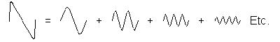
waves. For example, the following waves, when added, begin to look like
a square wave.
They are made up of only odd harmonics
of the fundamental (f1 + f3 + f5 + f7 etc. Count the number of peaks).
Whereas the following waves make a kind of sawtooth wave, made up of all
harmonics that lower in amplitude in proportion to frequency.
Is there a problem with this? Is this the true representation of a complex sound wave from a musical instrument? And is this what is really happening in an electronic device? Are the several sine waves actually being made? Or could our interpretation of this time honored and tested evaluation truly representative of reality?
With my limited knowledge I will attempt to explore these questions.
IS THERE A PROBLEM WITH FOURIER ANALYSIS?
Now, please do not misunderstand me here. The above question is more to get your attention and perhaps start you to thinking along maybe a different line. Fourier analysis is a time honored and tried and true way of analyzing naturally created waves of many types. I do not propose to dishonor it or make any grandiose claims of a better way. There isn't. And if there were I certainly would not be anywhere near as qualified as he or any other math student to find out what it is.
So before I continue, NO there is no problem with it. But there might be a problem with how we use it in electronic analysis. I am again going to state that I am not close to being as much of an expert as many in the field, I just am merely trying to point out a slightly different point of view.
Now that I think we understand each other, I will continue without further reassurances of my or your knowledge, or my sanity.
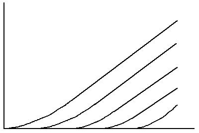
Take a signal from a theoretically pure sine wave generator. According to Fourier analysis it cannot be broken down any further. It is a pure sine wave. The formula Esin(2pift) represents this wave all by itself and cannot be added to or taken away from. Now we pass it through a single stage triode amplifier. The triode has the plate characteristic curves similar to below:
When used in connection with the transfer curve to plot what the output might look like, one gets the following:
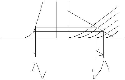
Notice the exaggerated negative peak of the wave at the output, on the right. It would be the inverted positive peak of the wave on the left. Assuming that the tube was biased at the curvy part of the transfer curve, the wave out might look like what is drawn on the right (redundant, isn't it!). This would be the distortion of the pure wave imposed by the tube due to the non linearity of the transfer curve. This would be a badly biased tube, in a badly designed circuit.
Fourier analysis of the resultant output wave should reveal a strong second harmonic, followed by a weaker third, then a slightly weaker fourth, etc. Personally, I see a bent sine wave, not several sine waves added together. But that's me. I am not all there upstairs, either.
So...
ARE THERE SEVERAL SINE WAVES ACTUALLY BEING MADE?
Since I answered the question of what is really happening in the electronics (the bending of a sine wave), I will skip it and go to the musical instrument question later. But for now, are there several sine waves being made in the device? This is what has made me curious all this time.
To make any kind of wave, one needs an oscillation. This is a fact. That is what a wave is, an oscillation or fluctuation of amplitude. In an instrument we set its oscillation by plucking it or blowing into it. The device uses the energy to make an oscillation. In electronics we make a tuned circuit or a tuned circuit with an active device and positive feedback (for sustained oscillation) and start it off with electrical energy.
But in an amplifier, we aren't oscillating the device. We are merely bending the shape of the wave in the process of making it larger. One might interpret the device's following the sine wave input as a sort of oscillation, because it is making a larger current/voltage to fluctuate in tandem with the input, but it is not making its own oscillations, per se, but following the oscillations of another source. So, are there extra waves being made? I don't believe so. But don't quote me or take my word for it. I am merely speculating or theorizing or fantasizing or what have you. We are merely interpreting the shape as being made up of extra waves using Fourier analysis.
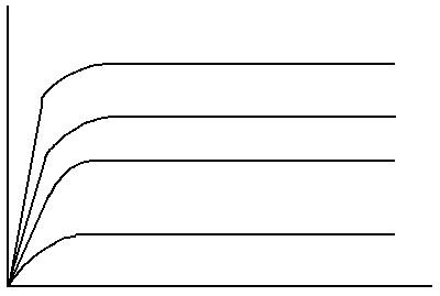
This shape changing can be similar in the bipolar transistor. Take the single bipolar transistor amplifier. There are two things I believe that are at play here. One is the shape of the collector curves. They are similar to the pentode. One notices that when the device is turned on, the voltage rises instantly to a peak and then levels off. The triode's curve rises slowly and then goes up. I call this a speed thing. I know, real lay person. But it does turn on fast. The pentodes (and tetrode. It also has a similar curve) claim to fame was its high speed (actually, it was higher frequency response, which is tantamount to speed. Frequency can be converted to time and vice versa). Anyway, coming from digital electronics, the faster the gate can switch on or off, the straighter up the up clock and conversely down. This makes for a sharper corner at the top of the duty cycle of a square wave.
This is the shape of bipolar, pentode
and tetrode curves, roughly:
The other, I believe, is the bipolar transistors unfortunate trait of base current. A typical common emitter bipolar amplifier's characteristics are determined by the Ebers-Moll equations. The input impedance is high "looking into the base" in parallel with the base resistors and the previous stage's load. However, it is this "looking into the base" thing that I am focusing on.
If for example the base's impedance is 100K ohms and the input signal causes an RMS current of one milliamp (actually, the collector current will be .99 milliamps, and the base will have a .01 milliamp current, where the emitter's current will be the combination of the two, or 1 milliamp) to flow from collector to emitter, assuming a beta, or base current to collector current ratio of 100, then the base's current will be 1/100th of the collector current. If one does some simple Ohms law calculations one will arrive at a voltage of 100 000 times .01 milliamp, or an RMS voltage of 10 volts "looking into the base". If the power supply was 10 volts, this will clearly make a square wave, since the peak to peak voltage "looking into the base" will be 28 volts! So, the transistor is manufacturing odd order harmonics from two characteristics. Hence their stronger odd order harmonics than even the pentode.
If one were to look at a square wave from a digital source on an oscilloscope, the wave would look perfectly square when set to a speed that showed several waves. But if one sets the scope to a higher speed (or a smaller time rate) then one would notice that the up swing takes a ramp approach. In other words the square wave starts to look like a trapezoid. The point is, if the device making the square wave were slower to turn on, the resultant square wave of the same frequency would look like a trapezoid at a much lower speed of the scope (or higher time rate). The edges might also be rounded. Fourier analysis would have us believe that even harmonics were being made and dominant (again, to me I see one wave).
This is the interesting thing about the push-pull circuit. Since the tube only needs to take care of half the wave, and since the highest velocity of a wave is reached at the zero crossing of the wave, the tubes are cut off and turned on relatively quickly. So the result is a faster speed, hence the Fourier analysis of odd harmonics dominating in a push-pull circuit. In my opinion, anyway.
Also, since each tube takes care of half the wave (in class AB or B. Each tube amplifies the full signal for class A push pull amplifiers, but the symmetry is maintained due to a mirror effect. That is, one tube has the mirror image of the other as its signel and the errors cancel each other out, hence a low distortion output), there is a symmetry that is maintained. The half of a wave is amplified throughout the range of the tube's or transistor's curve. If the entire wave were being amplified then the bottom half would be subject to the lower part of the device's curves and be altered differently from the top half of the wave. This would result in asymmetrical amplification of the entire wave. But the push pull circuit keeps the wave in symmetry, hence the cancellation of even order hamronics. Basically in many tubes the lower half of the wave is squished. Fourier analysis says this is the result of even order harmonics being added to the wave. I say it is just being squished on the bottom (I guess I am repeating myself to try to convince you. Maybe! ;-) ).
Many claim that single ended amplifiers sound most musical. The distortion is filled with pleasant sounding even order harmonics. Well, what is really happening is that only the bottom half of the wave is being cut off (the definition of all even order harmonics in a wave is a half wave!). In a push pull amp both halves of the wave get cut off, hence the unpleasant sound.
Now...
IS THIS THE TRUE REPRESENTATION OF A COMPLEX SOUND
WAVE FROM A MUSICAL INSTRUMENT?
This is a tough one to answer. I don't know. However, there is a web site where a student has analyzed the tone from several sources, in particular bells, that show the relationships of the harmonics to the fundamental. Interestingly the proportions were such that for a bell the second harmonic was strong, the third was lower, the fourth even lower and so on. The flute was strong on all the even harmonics. Does this mean that Fourier analysis is correct in this case?
According to work done by Russell O. Hamm, I would say yes. He did research that included manufacturers of pipe organs. What he found out was that they purposely added even order harmonics in order to make the sound of the thing more pleasant! So, it works for natural sources of sound to be sure. And for heat waves.
The conclusion here, though, is that the source of musical sound is actually making the harmonics. This can easily be demonstrated by certain techniques to make a string of a guitar or bass to make a harmonic of its open string fundamental.
The difference here, however, is that the harmonics do not necessarily remain in constant phase in relation to the fundamental. In other words, the harmonics can vary in phase over time, due to the instrument being a nonlinear system. The string of a guitar, for instance, changes tension over its range of motion, hence causing the harmonics to vary in speed as they travel along the string, hence varying in phase and frequency. Our hearing mechanism cannot detect variation in phase (except under certain specific conditions. The Psychology of Music), so this is more than just a plausible assertion.
Take the fact that there are phase shifts in amplifier circuits. If the phase relationship were so important, we would be able to hear a marked difference in the sound of an instrument. Yet we can tell what a guitar is or a drum or a flute in reproduced sound. Therefore the conclusion is that the harmonics' phases vary with relation to the fundamental as a function of the instrument.
Picture this: A string on a stringed instrument is plucked. According to most physics books, the string initially produces all waves, until they reach either end, are reflected back and then cancel out all but the fundamental and harmonics, which then remain in a fixed position, or a standing wave. This is what is accepted and taught.
But now imagine this: first of all,
a guitar or any other string is seldom if ever plucked at the center of
the string. (I have tried it myself on my guitar. The tone is different
when I do pluck it in the center of the string as opposed to the normal
location above the hole, about 1/5th the way from the end of the string.)
So the above condition could not completely happen, because the waves do
not reach the ends at the same time and therefore do not reach each other
at the center to cancel out completely. But let's say that we pluck the
string near one end as most people do. Now we have a string that has an
initial wave that starts at one end of the string and travels to the other
end of the string. At the same time the string is moving back and forth
at what we know to be the fundamental of the string. All the while the
string is also making other harmonics. But the harmonics are also traveling
back and forth along the string.
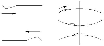
In the above picture, on the left is a string that has been struck on one end. The strike produces a pulse that travels back and forth along the string. The image on the right is the same string now moving up and down at its own "fundamental". As can be seen by the vertical line, there will be a time when both waves are at their highest peak at the same time.
The point here is that the phase of the harmonics can vary. Fourier analysis implies a fixed phase for each frequency. However, the fact remains that the string is actually making two (many) distinct waves, as opposed to the above demonstration that the electronic device is only bending the shape of one wave. So, two conclusions are drawn here. One is that the phase of the source of sound is not being correctly ascertained by Fourier analysis, and not a true factor in the sound quality of an amplifier, which leaves the second thing. The amplitude of the harmonics, which is an important function of both the timber of any instrument and our hearing, as brought out in "The Psychology of music." More on this second point later.
ONE POINT OF VIEW OF HAMRONICS
Interestingly, what can be done here is look at the pattern of musical harmonics. If the flute and bell and most musical instruments for that matter, show a pattern where the second harmonic is strong, then we should be able to match these with the "harmonic" distortion properties of the amplifier under test. What do you suppose the conclusion will be? The pattern that matches the one for natural musical sources will sound most natural.
I believe that that is the reason tube amplifiers seem to sound louder and more natural, or musical, than solid state amplifiers. The harmonic pattern that the tube makes from the fundamental causes it to add to the harmonics already in place by the source. This addition causes a psychoacoustic effect that the signal is louder than it actually is.
Picture this: the fundamental is at 10 volts. Then the second is at 6 volts. The third is at 3 volts and the fourth is at 2 volts. Let's say that the tube "adds" its harmonics of the fundamental by about 10 % for each. So now the second is 6.6 volts, the third is 3.3 volts, the fourth is now 2.2 volts. According to The Psychology of Music, we can hear these slight changes in the amplitude of harmonics. Now, the harmonics are disproportionately larger than the fundamental, correct? Ah, but our brains reconstruct fundamentals from the harmonics alone, so now we psychoacoustically hear a fundamental that is larger than it really is, because we psychologically add to it by the fact that the harmonics are louder!
ANOTHER POINT OF VIEW
The preceding assumes that the amplifier actually makes the higher frequency sine waves, which is unlikely due to what I mentioned regarding amplifiers versus oscillators.
The other more likely explanation is the fact that the grid of a tube is a very "stable" load to the previous stage. Impedance is generally determined by the grid resistor and interelectrode capacitances are generally constant throguhout the signal voltage swing and frequency range. This ensures that the amplitudes of the fundamental and harmonics remain constant in proportion. This is the aforementioned criteria for our hearing mechanism, the amplitude of the harmonics. The bopolar transistors input changes with both frequency and amplitude of the signal, causing oit to vary or be less stable with regard amplificatioof the fundamental versus the harmonics. In other words it creates an imbalance of the amplitudes of the haemonics. That plus its susceptibility to clipping of the internal signal "looking into the base", makes for a less than desirable sound quality.
The FET and the MOSFET both have tube like input junctions and are therefore more desirable as solid state devices forthe amplification of music. But they too have certain limitations wich make them less than desirable as opposed to tubes. However, on my Solid State Tube page I have a solution.
Now, remember the diagram of the fundamental and the harmonic joining at one point to create a peak? It is this peak that we percieve as the power of the instrument. In a tube amplifier since the fundamental frequency and the harmonics' amlitudes are maintained, this peak can also be relatively maintained throughout the amplifier, hence the percieved loudness and punch of a tube amplifier. Solid state amplifiers reduce the amplitude of both the fundamental ( the highest amplitude in most cases) and the resultant periodic peak. Hence the transistor amplifier's lack of punch.
CONCLUSION
We have now two factors in favor of the triode regarding harmonic distortions. 1) The Fourier derived harmonic pattern of the triode is similar to natural sources of music and adds to the harmonics of the music in proportion, making for a perceptibly louder output. 2) And the input of the tube does not load down the previous stage such that it alters the harmonic amplitude proportions. Which one you subscribe to is your choice.
But as for the device of choice? The
tube wins this contest.
Copyright 1999, Gabe Velez