This is such an in depth subject that I will reserve my input to this component to more basic explanations and leave the permeability and make-up of core material, magnetic flux density, shunt capacitance/inductance, electromagnetic theory and the like to references.
I will instead concentrate on the more basic functionality of output transformers. Power transformers are pretty basic and the things that are necessary (read "basic knowledge." There is more but not necessary to fully know to make a good power supply. This is covered in the power supplies section) to understand about them is turns ratio and power handling (for example, the voltages of the secondaries versus the current).
However, in audio circuits, a good understanding of the two types of output transformers is necessary to make a good choice for the best sound and efficiency.
WHAT IS A TRANSFORMER?
As the word suggests, a transformer transforms one thing in to another. In this case we are transforming one level of voltage and current to a different voltage and current. With that we are also transforming one impedance to another. Before I go on it is necessary to remember that transformers work with AC only. Nothing will happen if a constant DC is used. The AC induces a varying magnetic field into a coil of wire that also reinduces a current into the wire. This is known as self inductance. However, the coil can also induce a current into another coil.
A transformer is made using many windings of copper wire that is coated with acrylic to allow for insulation while allowing the wire to be as close as possible to itself in the winding. This only makes one coil of the transformer. One needs a second coil of wire with properties (number of windings) that make it convert the first coil's characteristics. In other words, if the first coil has 5000 windings, and the second coil has 1000 windings, then it is said that the transformer has a turns ratio of 5 to 1 (5:1). That means that if I put an AC voltage of 100 volts on the first coil, also known as the primary, then the induced voltage on the second coil, also known as the secondary, when placed next to the primary will have a voltage induced to it that is 1/5th the size, or 20 volts AC. This is known as loose coupling.
The thing that allows transformers to conduct from one coil ot the other is the sharing of flux. This is known as mutual inductance. The air is the conductor of magnetic flux in this case. One can only get a certain amount of power this way. Air has a permeability (allows magnetic flux to conduct) of 1. Iron, on the other hand, has a permeability of about 1000 or more (steel goes up to about 5000). If I were to place a piece of iron in the center of the coil, then the lines of flux will be concentrated (because more magnetism can conduct easier through it, like the path of least resistance) and more power could be transferred to the secondary. What happens here is that more flux lines from both coils share the same path, or both coils have common lines of flux. This is what coupling means. If I make that iron core common to both, then more power can be transferred still.
Old style radios (in the 10's and 20's) used two separate coils connected by a "U" piece of iron as the common core. But there is an even more efficient configuration that is now used that also makes the transformer more compact. It is the practice of winding the secondary coil directly on top of the primary (although there are still some transformers that have two separate coils that use a common core). This allows the lines of flux to cut through the secondary directly and more instantly. This is called unity coupling.
So now we know about turns ratio and its direct connection to voltage transfer. But in the voltage transfer there is an interesting thing that occurs. Current also changes. If I put that 100 volts into the transformer of 5:1 ratio the voltage drops to 20. But if that 100 volts came in as 1 amp, the secondary can provide up to 5 amps! This is the conservation of power rule that transformers must follow. Of course, this is not exact, since there are losses that occur in transformers, as will be discussed later. This applies to all transformers and there are of course a few more factors that come into play.
For example, a transformer rated at 12.5 volts output at 100 milliamps only means that the wire is thinner and there are many more windings. BUT the turns ratio is still maintained. So the primary of 125 volts only drains 10 milliamps, because the turns ratio is 10:1, so the input current is 1/10th of 100 milliamps.
IMPEDANCE IN A TRANSFORMER
There is a reflected impedance back to the primary that occurs from the secondary and the source, in this case speaker and the tube. That is why many say that there is a better damping from a triode than a pentode, because the transformer reflects the triode's plate resistance A.K.A. its impedance. So we do not need to worry too much about that. However, the reflected impedance from a speaker as a load does vary nonetheless because speakers are not constant impedance loads and can vary from less than one ohm to more than 40 ohms. Ideally though the primary impedance is constant and is proportional to the turns ratio by the formula:
Zs/Zp = (Vs/Vp)^2
This states that the ratio of output impedance to input impedance is the same as the ratio of output voltage to input voltage squared. So, if the impedance ratio changes, the voltage ratio changes by a small amount.
For example, let's use the common impedances of 5K for the primary and 8 ohms for the secondary of a single ended amplifier. Lets use 320 volts for the power supply. Now assuming typical values for the output tube, lets assume that 20 volts will be dropped across the tube/cathode resistor during normal full output swing. So we have 300 volts peak to peak, which translate to 150 volts peak. Multiplying 150 by .707 we get the RMS voltage at the primary. This comes out to 106.5 volts RMS. With this info we can substitute the variables and derive the secondary voltage with impedances as they are. (We will assume that the plate resistance is high enough not to affect the primary impedance too much so we use the 5K as is. Real world values will vary due to plate resistance and load). So we now plug in the known values to the formula and do some algebra to arrive at the secondary voltage (sqrt means square root):
8/5000 = (Vs/106.5)2
sqrt(8/5000)=Vs/106.5
[sqrt(8/5000)] X 106.5 = Vs
0.04 X 106.5 = Vs
4.26 = Vs
Now that we have the secondary voltage out we can check this by plugging all the now known values to the original formula:
8/5000 = (4.26/106.5)2
0.0016 = (0.04)2
0.0016 = 0.0016
From this we can see that if a four ohm speaker were put into the eight ohm output the primary impedance will change by the proportions involved. Lets see how that works, assuming that the voltage ratio's don't change, since the voltage ratio is directly proportional to turns ratio.
So we have the known values 4 ohms, 106.5 volts and 4.26 volts (this gets hairy!):
4/Zp = (4.26/106.5)2
sqrt(4)/ sqrt(Zp) = (4.26/106.5)
sqrt(4) = (4.26/106.5) (sqrt(Zp))
sqrt(4)/(4.26/106.5) = sqrt(Zp)
2/0.04 = sqrt(Zp)
50 = sqrt (Zp)
2500 = Zp
So, interestingly it seems that the proportion one would expect occurs when the impedance of the secondary changes. A direct proportion occurs. Going from eight ohms to four ohms (halving) actually lowers the primary impedance by the same factor, namely in half. This keeps the power transfer the same, because halving the primary impedance causes the effective current to double. But reflected impedance could still go as low as 625 ohms if the speaker impedance goes down to 1 ohm for a given frequency.
This is pretty much true for solid state also. Since the voltage levels are constant, the current is what changes. Good old Ohms law!
PARALLELING TUBES
So now, what if the opposite were true? What if I double the output tubes? Some have argued that doubling the output tubes have no effect on output power. Let's take a look at this mathematically.
Let's assume a plate resistance of 22500 (for a 6l6GC. My current pet output tube) in parallel we use the ole parallel formula. Actually it's easy because it is merely half for two tubes. So we get about 11250. In parallel with the primary, though we get a different result. This is the formula for paralleling two unlike values:
R1XR2/R1+r2
11250X5000/11250+5000
5625000/16250
3461
The Primary impedance now becomes 3461 ohms. So the reflected output impedance is about 5.2 ohms. Now, judging from this, what is the power? The voltage still remains at 106.5, so using a little ohms law we get a current of 106.5/3461, or 30.7 milliamps. Not a lot, is it. 106.5 times 30.7 milliamps is 3.2 watts. Not much. Let's see what it was originally.
With the above assumptions, namely the 6L6 (22500 ohm plate resistance) and a 5000 ohm primary we use the parallel formula and get a primary impedance of 4090 ohms! Pass 106.5 across this and we get 26 milliamps! So we have a power output of 2.7 watts! Not a doubling of power, but an increase of half a watt, but an increase none the less.
However, it is noteworthy to add that I am calculating these levels based on an unbypassed cathode resistor in a cathode biased amp. Bypassing the cathode resistor decreases the plate resistance, hence impedance.
So this puts to rest the argument that double the tubes gives double the power. However, in order to take advantage of the doubling of tubes, one needs to half the input or primary impedance of the transformer. Since power through a transformer must be identical on both sides (barring intrinsic losses), this is possible without increasing voltage. So assuming that both tubes combined allows 30.7 milliamps through at 106.5 volts each, the output power will be 6.4 watts. But this means that the primary impedance must be 2500 ohms. The turns ratio will be different, allowing for the current ratio. Current ratio is inversely proportional to turns ratio. In other words:
Np / Ns = Vp / Vs = Is / Ip
Where Np and Ns are the turns in the primary and the secondary respectively, Vp and Vs are voltages and Ip and Is are the currents. If we really want to go crazy, we could calculate this all the way (impedances, voltages, etc.), but I think you can use this as a practice example for yourself.
TRANSFORMER LOSSES
As I said before I will leave core and magnetism theory to the textbooks. But I will mention that the core materials, winding practice, and wire quality all come into play where sound quality is concerned. That is why there is (relatively) so much of a variety in manufacturers and within manufacturers as to the transformers cost and type.
One of the losses that occurs in a transformer is known as eddy currents. What happens is that the current that flows through the coils induces magnetic currents within the core material. This in turn induces a small current back into the coil. It is very similar to self induction. This however causes two of the problems. One is to lower the current transferred to the secondary, so this is a current loss, and it generates heat within the transformer. This is heat loss. This is one of the reasons why the transfer efficiency is 80-90%.
Another loss is stray capacitance.
As with any conductor, if it runs close to another conductor in parallel,
they will have a capacitance between the two. A transformers windings are
many parallel wires. Then there is capacitance from primary to secondary,
and from both to the core, which in most cases connected to the chassis,
or ground. This limits high frequency response.
There is also a phenomenon
called hysteresis. This is a delay that is caused by the time it takes
for the core to magnetize and release its magnetism. Different formulations
of iron or steel have different degrees of hysteresis. Unfortunately the
formulations that have less hysteresis also do not perform as well. So
a balance must be maintained. Hysteresis causes phase distortion in the
low frequencies. This is not the same as the hysteresis used in some circuits
to speed up their switching time. That is a form of positive feedback.
SINGLE ENDED AND PUSH-PULL TRANSFORMERS
The single ended transformer is an interesting beast. Talk about compromises! There needs to be a balance of power and frequency response here. Make a single ended transformer produce a full range, and one needs to sacrifice some power. Make an SE transformer for power and frequency response suffers. There have been some very good posts on the news group rec.audio.tubes about the technical aspects of this relationship.
The frequency response of an SE (low frequency) depends on the primary winding inductance. In order to get a large inductance one needs to add windings. This can lead to saturation easier, though. It also leads to a higher impedance and lower current. Lower power. To lower the ill effects, less windings are needed, but this reduces low frequency output. What a dilemma. So we need to focus on a happy balance.
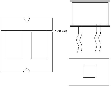
In the SE design, one needs to take into consideration the saturation point of the transformer. If one biases the output tube past the midpoint, then they run the risk of saturating the core, causing distortion, similar to clipping. The reason for the precaution it because there is always a single direction DC current making the transformer into a single magnet. I am using the word single because in a push pull transformer there are two flows of current, but more on that later. So in essence we have a fluctuation of magnetism from midpoint to full to none, which corresponds to the midpoint flow of current, to full current to none. The same is the case with voltage. The saturation problem is minimized by several techniques. There is winding, core material, and a small gap. This gap is put between the I bar and the E portion of the transformer. (Fig. 1)
In push pull transformers, there are two sources of current. However, the flow is in opposite directions, so ideally, the magnetism cancels out. This makes for no core saturation problems. This also allows for the construction of smaller transformers for the same power level. However, there are other problems associated with push pull transformers. Some speak of a magnetic form of cross over distortion. However, I think that this is more related to the output tubes' crossover distortion. NFB takes care of much of this anyway.
Then there is the reduction or elimination of the sweet sounding even order harmonic distortion. I have yet to find out why this occurs, except to surmise that the even order components are in phase, while the odd order components are out of phase. So the even order components cancel out in push pull while the odd order reinforce each other. I think in the strictest sense that the real effect has to do with the speed that the components reach saturation and cut-off as opposed to pure Fourier analysis, but that is discussed on the distortion page.
Here is a couple of posts by Mike LaFevre of Acrosound about some particulars of transformers. I think it is pretty interesting and in depth.
CONCLUSION
So, to SE or not to SE, that is the question. I personally prefer push pull, but I have made a SE amp and find it to have some desirable sonic qualities as well as surprising power.
There are quite a few manufacturers of quality power and output transformers available. Here are a few manufacturers and vendor of them. Note: they are in no particular order:
Manufacturers:
One Electron
Lundahl
Magnequest
Hammond
Vendors:
Antique Electronic Supply
Triode Electronics Corporation
Acrosound
Communication Jute
There are many more of each,
but these come to mind as being the most popular. They can all be found
at my links
page.
Back to Papers page