So you want to build a directly Heated Triode amplifier and would like to spend as little as possible, huh? This amp might be the ticket for you.
Let's say you have a junk box full of capacitors, resistors and even a couple of single ended transformers and a power transformer. You have the above two choices for the power output. As many DHT SE amp gurus, as well as the dealers who may stock em, know the price may vary from $35 (US) used to $100 or more NOS (New, or unused, Old Stock) apiece! I don't know about you, but even though I can afford them, why should I spend so much?
Now, I personally do have a few 45's laying around in my antiques. But I really do not want to use them. Chinese 2A3's however are reasonably priced. And I understand that they sound very good, too. In the mean time, though, I would like to hear what a DHT SE amp in a hi-fi scenario sounds like.
So I have relatively decent output transformers, which have a primary impedance of about 3500 ohms. From what I have read, that is good enough for either tube. I have some 4 pin sockets, a 6SL7 (a 12AX7 would do nicely too). A bunch of resistors and good capacitors. I also happen to have a 300-0-300 volt power transformer with a 5 volt 3 amp, and three 6 volt at 3, 5, and 7 amps apiece filament secondaries.
Man, I forgot! The 45's and 2A3's have 2.5 volt filaments! What is a person to do! Ah! I know! String them in series to get a 5 volt filament! This way I can substitute either tube without worrying about the tremendous current difference! 45's are 2.5 volts at 1.5 amps. In parallel, which is the way they are connected in circuits using one filament transformer for both that makes three amps. The 2A3 has a 2.5 amp filament for a parallel current of 5 amps. But in series, they both need five volts across and will drain only 1.5 amp for the 45, and 2.5 amps for the 2A3. A 5 volt 3 amp secondary will suffice.
But what do I do about the rectifier? Doesn't it need the 5 volts? Sure does. But I am not using a tube rectifier here! I am going to use a solid state bridge rectifier. Why? Because a power supply should have NOTHING to do with the sound quality of the amp. Well, it does but only such that it supplies plenty of power for full output operation, with some reserve to spare. In other words, the power supply must provide sufficient power to maintain a constant voltage over a varying current demand. If not then the power supply is inadequate and will cause changes in the sound quality of the amplifier. This is undesireable and a folly of those who claim that one rectifier tube sounds better than another, or that tube rectifiers sound better than solid state ones.
Tube rectifiers tend to change (lower) the voltage with higher current draws. This is because they have an internal resistance. Using Ohms law shows this easily. It is the job of the filter capacitors to minimize this by being large enough to compensate for the current draw. I use 300 microfarads, about 10 times more than most tube audio manufacturers used to use, for my amplifiers, whether they use a tube rectifier or a solid state one. Solid state rectifiers, however only drop about 0.6 volts ( some high current ones can drop up to 4 volts, but this is still not much compared to 30-50 volts for tube rectifiers) regardless of the current draw.
Also the other reason I am going to use a bridge rectifier is to make a negative voltage supply for fixed biasing the output tubes. Since the kind of configuration I am using does not allow much for self biasing, I can use grid biasing to keep the output tubes working class A.
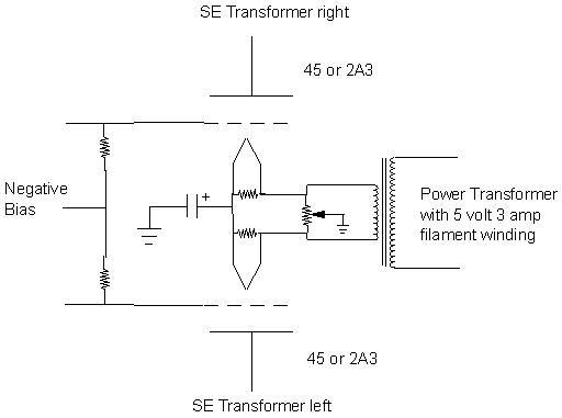
Here is a schematic of the one I designed. The heart
of the simpleness of it is the output stage and power supply. You can use
just about any driver as long as it can provide about a 60 volt p-p output
for full power output.
The only problem I could foresee is not getting a stereo image. However, I did an experiment with my 6L6 SE amp that showed I can still get good stereo separation with a bypassed common cathode resistor. So, on with the experiment.
I will be hooking this up together soon, just to see if I can get a decent balance of filament voltage. I assume that the resistors in parallel with the filaments will keep voltages relatively equal, but that may vary depending on the filaments. The capacitor from the junction of the two filaments to ground should provide a path for AC to ground so as not to be injected into the cathode/filament of the other channel. I believe that I may need to have a resistor across the capacitor to ground to provide a cathode bias through the tube with B+ in mind, as opposed to the obvious filament voltage. The pot at the 5 volt taps should provide some sort of hum balancing.
For those who think that the filament transformer
needs to have a center tap, not to worry. There are many designs I have
seen that do not have a center tap, but use instead a hum balance pot.
I think this particular design will work out remarkably well because instead
of going through the filament windings or balance resistors or hum pot,
the signal and bias voltages will go directly through the common resistor
at the junction of the filaments.
More to come soon.