MY FIRST TUBE AMP REVISITED
We want to take a look at the first tube amp a little closer. In that project I used the 12AX7 as an example. The calculations and settings are pretty much what one does, but things vary. Different tubes have different responses in bias settings. If one were to look at the plate curves of triodes, one will notice that for a given plate voltage, a certain current will flow, and vice versa. You may find that the plate voltage desired does not happen when using the design philosophy I spoke of on My First Tube Amplifier page with tubes. I have. So what does one do?
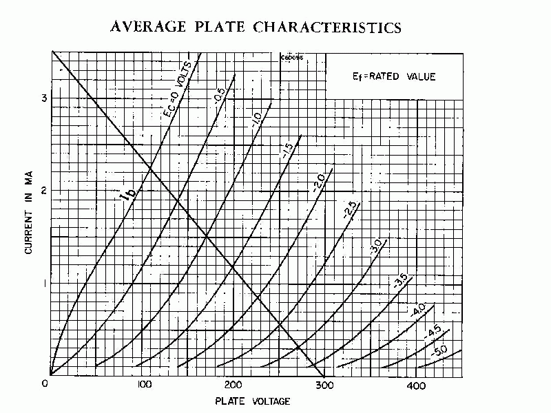
One uses the Static Plate Characteristic curve chart. In my first tube amplifier we actually discussed dynamic characteristics. It was a primer to get you familiar with both tube characteristics and functions, and designing circuits. This chart helps us to determine static characteristics, or quiescent (no signal) bias settings.
This is how to do it:

Since the tube is the "active" component, this variance of plate resistance is a good thing. This is what makes the "voltage divider", made up of the tube and the fixed load resistor, vary voltage level. So as the input varies a little, the output current varies alot (remember transconductance?), causing the plate resistance to rise or lower, which causes the voltage at the load resistor to also vary. This is the output representation of the input, but at a larger scale (from 0.5 volt in to 14 or 15 volts out), as can be seen from the chart.
Now we are going to get deeper into the mud. So, looking at where plate voltage will be for a certian grid voltage on the chart, let's say minus one volt, and then look across horizontally to the current level we want and divide the voltage by the current, you will get the plate resistor value needed. With the same current level one can calculate the cathode resistor by dividing the one by the current. So if the current is 1.5 milliamps, then one divides the plate voltage that corresponds to where the grid voltage and the current intersect. We have about 175 volts when going down from that point. So the plate resistor should be 175/0.0017, or about 117 K ohms. Then using good ol' Ohms Law one can also calculate the cathode resistor to set bias for that plate voltage. So let's take the line above. It intersects at the point we want our plate voltage and current to idle at. But it also shows where that same current and grid voltage we want it to idle at, the positive form of which should be the cathode voltage. So for minus one volt at the grid that means that we need to drop about one volt at the cathode resistor. So 1/0.0015 is 667 ohms. We can get 120 K and 680 ohms for the plate and cathode resistors respectively. I used 100K and 680 ohms.
Me, I am a fanatic about linearity. So I choose a point on the chart that will give me linearity. That is why I chose the above settings. I did it for both my SE amp and my push pull amp. The 6SL7 and either the 6EU7 and 12AX7 all sound very good at those settings. I do sacrifice some longevity, but the sound is worth it. So instead of using the same tube for 15 years I need to replace it after 8 years... so what.
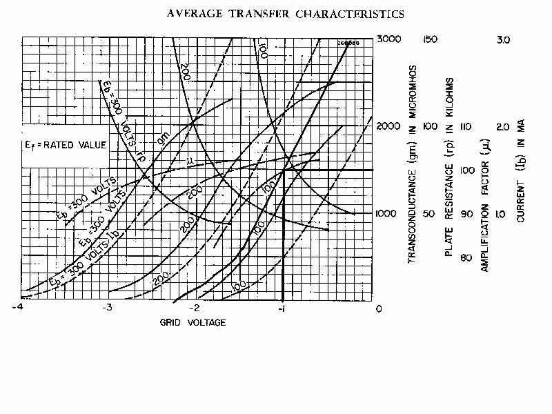
If I showed the transfer curve also,
you would see that it is pretty straight (not curved) at that level of
current. In fact I will. Below is the transfer curve. That is what the
transconductance shows. Also the spaces between the plate curve lines (the
above chart) at the different voltage levels are even. So, it is the most
linear part of the tube that I can get. The actual values turned out to
be 176 at the plate and 0.76 volts at the cathode. Why that is is still
a mystery to me, but I suspect grid leakage. Changing the grid resistor
should reveal this. The grid-cathode circuit may make up a voltage divider,
hence where the cathode resistance (1/Gm) comes into play.

Messy looking, isn't it. Let's concentrate on the dashed lines and the plate current. The dashed lines represent plate voltage. Since we are at about 175 volts, I drew a separate line to illustrate the curve we encounter with our example above (I know, it isn't even and the curve is sloppy, but I can't draw anyway!). I also drew the idle current and voltage lines to show where they intersect with the transfer curve. As you can see the curve is pretty straight there.
Notice too that the transconductance seems to go up as the line goes up. Therefore, as the input voltage brings the tube closer to zero, the transconductance goes up, even though the plate goes down. Therefore, using the calculations for gain as we previously did on "My First Tube Amplifier" page, we will notice that the amplification factor, or Mu, remains relatively constant.
We can get so much deeper into this but it is beyond the scope of these pages.
Also, gain is pretty good there because I have a small value cathode resistor. So for 100K (what I actually used) and 680 ohms at the cathode, gain for that stage, with a 470K following stage, is about (62500||100000||470000)/(625+680) or (35553/1305) or 27. Not too shabby.
THE GRID RESISTOR
Here is one thing I did not mention on the My First Tube Amplifier page. The grid resistor value must be chosen wisely. I have had the experience that with no grid resistor the bias does not get set the way I want. It may vary with the value of resistor. A fixed cathode bias will allow you to not need a grid resistor. But one needs one for a cathode bias. In fact, if you look at the spec sheets, there is a recommended maximum for both fixed and self bias. Therefore, considering the so called rule of thumb about making the following stage about ten times the load of the plate resistance of the first stage, one needs to keep in mind that this is not always practical. There is a maximum. Why? Because there is a level of voltage that is set at the grid that is there because of what is known as trickle current. This is because the flow of electrons occasionally causes some to accumulate at the grid. If the resistor there is too high, this causes the bias to change, because the resistor is not allowing this current to "trickle" away. This is undesirable. So let's not ever get over the maximum amount. For the 12AX7 I believe that with fixed bias the grid resistor should not exceed 500K and for cathode bias the grid resistor should not exceed 1 MEG.
In some tube manuals there is a resistance coupled chart which gives good values for desired voltages and currents. If you want to forego trying to calculate the values you want, this is the way to go. Personally it is more fun to try it myself. But then why wreck your brains if almost all of the levels and values have been done for you?
For my one tube line amp, I used the above settings I calculated and a 330K ohm grid resistor and it sounds very good.
OTHER THOUGHTS
Steve Bench has a set of pages that go over in deeper detail the use of these charts with regards loadlines but with inductive coupled amplifiers. Basically he has a triode amp hooked up with an output transformer. The design ideas are similar to resistive loads but not quite. He has some other interesting ideas also, and some calculations for harmonic distortions. The calculations for distortion components are easily seen by the location of the curent and voltage components of the signal versus their location on the chart.
Among other things he explains the effect of the signal on plate resistance. I mention it a little on the previous page, but he explains the problems associated with it and how one can design to optimize the peformance of the tube with relation to the varying plate resistance.
I agree with his opinion in that the
load should be equal to the effective plate resistance (which is dependent
on plate voltage, etc). In the case of resistive load I say so because
we want the plate to have about half of the power supply voltage for a
full output swing before clipping. In transformer coupling this is more
difficult to express because the DC resistance of a transformer can be
about 100-150 ohms or so. So the DC voltage drop may only be 10 volts,
showing almost full B+ at the plate, whereas with signal the impedance
takes over still allowing full swing.