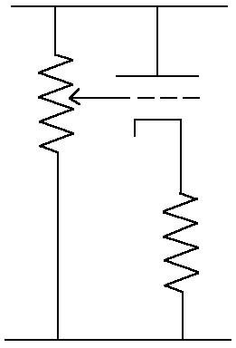
A conceptual hum minimizing circuit. This can either be right after the rectifier, in parallel with a filter capacitor, or right after the filter choke. The cathode resistor should be chosen to match the current of the ripple, derived from the equation Vr/Rl, the ripple voltage divided by the load. The current would then be used to determine the resistance by getting half the B+ and divide by current.
As an example, if B+ voltage was 400 volts, and ripple voltage was about 1 volt RMS, and current at idle was 100 milliamps, then the load is 400/.1, or 4000 ohms. a 1 volt RMS ripple would have a current of 1/4000 or 0.25 milliamps. So that our tube will idle at 200 volts across it with 0.25 milliamps, we divide 200/0.00025 and get 800000 ohms. Now, because we want to adjust it, we can use a 470K ohm resistor. The pot can be a 1 Meg linear taper. The nice thing is that this tube will dissipate only around 50-100 milliwatts. That means megalife for a 2 watt dissipation tube.
Now, the consideration that is needed here is that the filament would need to be tied with a resistor to the cathode, because otherwise the cathode to heater potential could be higher than the recommended maximum. This may be a problem if a separate heater supply is not to be had, therefore a small separate heater transformer may be needed. It may be possible to get away with this if one used a DC supply form the main AC filament supply only for the filter tube, or even capacitors so as to isolate the tube from the rest of the amplifier. This way one can supply the filament with the existing 6 volts and have the filament close to cathode potential.
The thought here is that the current of the tube would vary in tandem with the ripple voltage impressed at the grid. However the current of the tube would be out of phase with the ripple, hence minimizing ripple. Or one would hope so.
The idea is similar to the solid state voltage regulator where the base (corresponding to the grid) is at a fixed voltage set by a zener diode. The collector (corresponding to the plate) is directly connected to B+, and the voltage is taken from the emitter (corresponding to the cathode). Power supply ripple reduction is good due to similar ripple signals appearing at both the base and the collector, effectively reducing ripple.
So once we get our little circuit in place, we can then adjust it for minimum hum.
But then again, this is a concept circuit.