One of the most fascinating subjects in active electronics (tubes/transistors, as opposed to resistors/caps/coils) is biasing. Biasing is the static voltage and current settings for a given device for certain functions of operation. Depending on the needs of the circuit, there may be as many as six different biasing schemes. But for the most part there are four basic biasing schemes. They are Class A, Class B, Class C and Class AB.
Class A: This is where the device is biased at a point where it will conduct and amplify for the entire signal.
Class B: This is where the device is biased such that it will conduct for only half of the signal.
Class C: This is where the device will only conduct for a small portion of the peak of the signal. It can also be described as any biasing point where the device conducts for less than half of the signal. This biasing scheme is never used in audio and can be found in R.F. applications.
Class AB: This is where the device conducts for more than half of the signal but less than the full signal.
This is as far as I will go here regarding biasing classes. Here we will discuss practical implementation of the different biasing schemes.
With tube amplifiers, biasing has been the subject of many many articles and discussions on news group threads. It also seems to be one of the least understood subjects with regard tube sound.
Why does one bias setting sound "better" than another?
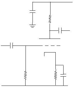
First, let us examine a simple single
stage triode circuit with a standard bias and bypass capacitor:
The above circuit is biased at the half points of the tube's maximum parameters. It has a nice sound to it and is loud but has some noise (hiss). However, at strong loud bassy passages, it tends to seem limited but warmer. Sometimes it even seems to drop out. Why is this? Some would claim insufficient transient response from the power supply. It sounds slow, as many would say.
But let's take a closer look at this circuit. Let us rotate the circuit 90 degrees to the left. Now let's remove the grid circuit for a minute.
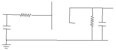
What does it look like now? That's right, a power supply rectifier! A half wave rectifier to be exact. So now what do the cathode resistor and bypass cap look like? A load and filter. The bypass cap sees a constant DC signal accompanied by an AC component. To a filter cap, or any capacitor for that matter, this appears as a fluctuating DC, or power supply ripple!
To get a bit deeper into the physics of the thing, if one were to calculate the time constant of the RC circuit at the cathode, one will find that for the above circuit the time constant is t=RC, or for the sake of argument, we will use the values I used for the actual circuit, 2200 X .000022 (22 microfarads). The answer is .0484 seconds. What that means is that the capacitor resistor circuit requires about .0484 seconds to charge 63 percent of its full capacity. For the first .0484 seconds, if the capacitor were a 25 volt capacitor, and the bias were set to 2 volts, it would only take the first time constant to reach 2 volts.
.0484 seconds factors out to a frequency of 20 hertz (1/t). If I took a 20 hertz signal of .7 volt RMS and inserted it, the positive peak will be 1 volt above the bias of 2 volts. Since the time constant is as small as it is, it wouldn't take much to increase the voltage of the capacitor. This also simultaneously changes the bias of the circuit by about .4 volts (0.404 X Vpeak. The average of the positive portion of a sine wave). Looking at the curve chart below for a triode, this will change the characteristics of the tube which is then amplified through the tube. A larger capacitor will do this more and make things worse.
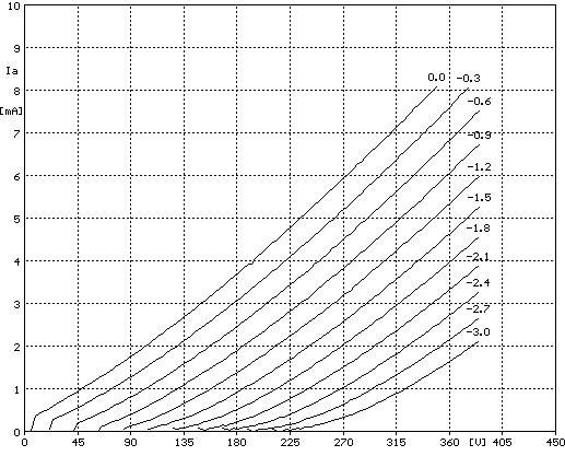
Looking at this chart, go to the 225 on the bottom line. This is the B+. Then go up to the 2.5 line from the left (the Y axis). This is the quiescent, or no input signal, current. For these conditions, it is showing a -1.4 volt grid bias. If the bias were anything different, then one would have to follow the line in the following chart to see the amount of voltage swing the input would accept before clipping.
A method for biasing a tube is to draw
a line from the B+ voltage to the desired current and choose a bias setting
accordingly.
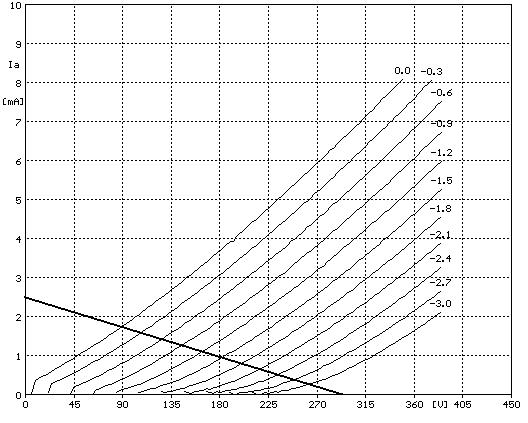
This line is drawn for the modified version of the above circuit I currently listen to. The B+ is 290 volts and the current is about 2 milliamps. If you were to place a pointer at the bias point you designed the amp for, and follow the line, you will see the varying current and the voltage it will produce. Say I had biased the tube for 1.5 volts ("I had a biased point for 1.5 volts"). No I didn't mean for you to say it! I start at 1.5 volts on the line, go to zero and I will see that the plate voltage has gone down to 50 volts, while the current went up to 1.8 mA or so. Then I take the voltage down to -3 volts. This would be a full peak to peak input swing. We can see that the voltage went to about 260 volts, where the current went down to about .3 mA. So the conclusion is that we use the above graph to set static voltages and predict to a relatively good degree the gain. So the output voltage swings about 210 volts peak to peak. This makes it about 74 volts RMS. So the gain can be calculated as Vout/Vin, or 74/1.06= about 70. Theoretically, that is.
For the sound quality we want, we need to use a transfer chart in conjunction with this one. It is a chart which shows the relationship between grid voltage and plate current. If we bias the tube along the most linear part of this line, and follow it with a nominal voltage swing across to the above chart, then one can find where clean signals end and clipping begins. Unfortunately I do not have a true chart, but the below will illustrate what I mean.
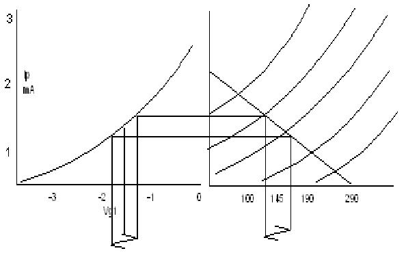
The diagram assumes accuracy, but it is not. The transfer curve is usually straighter in the area above the near cut-off region (depending on the tube type). However, if the circuit parameters are B+ 290 volts, Vp 145 volts, Vg -1.5 volts and Ip 1.5 milliamps, then a grid signal of about .75 volts peak to peak will output a plate voltage of about 45 volts peak to peak. That gives a voltage gain of about 60 according to the above chart. Actual gain is not like this, but circuit parameters might cause a higher or lower gain, depending on the design of the tube and the resistors chosen for biasing. A fixed bias circuit could allow for the resistors to set gain by the simple gain equation G=Rp/Rk. If the plate resistance is 65 kilohms (this assumes total plate resistance, covered on My First Tube Amp page) and the effective cathode resistor is 680 Ohms, the gain could be 100, and the grid bias can be exactly 1.5 volts. Certain tubes have a top gain (12AX7 and 6EU7 for example) of 100. This is known as the tube's amplification factor or mu. The curve on the left, which is the transfer curve, is actually more curved as one approaches the more negative voltage level. Biasing down there will not yield a very linear response. So fixed biasing has its advantages, one being the possibility of not using a bypass resistor. Another is accurate biasing that doesn't change much with time or heat, providing better linearity.
In audio, with one instrument or even the fundamental being at a high amplitude, the instant that the peak reaches this area, another signal of a higher frequency may suffer the effects of distortion. This is a form of modulation distortion.
Capacitors cause current to lag the voltage, so the bias will not follow the signal, hence altering the incoming signal's nature, and the overall sound quality. What this means is that a signal whose current component and voltage component are in phase will come out of a capacitor with current being 60 degrees behind the voltage signal. This may not necessarily be a problem if there is no grid resistor (some circuits do this), but if there is a grid resistor, then the resistor will react to the varying current and add to the original voltage signal the resultant voltage signal across the resistor and cause a slight phase distortion.
This is because, not only do the biasing schemes mentioned at the outset of this discussion alter dramatically the sound quality, but also variations within the most popular, the class A, also alter the sound quality. You will find that the schemes that use the lower voltages and currents are more popular because they are the least linear. This may seem like a contradiction to what an audiophile would want from a sound system, especially one that uses tube and expensive irons. It is.
Being a purist who is also a tube lover, I find this to be perplexing. In my opinion, wherever the tubes are biased, it is still far superior to many solid state high end designs. It takes many transistors in a circuit to come close to the amplification ability and linearity before distortion reducing schemes that it takes only one twin triode to do.
I have seen specs for an amplifier configuration using a 6NS7 tube (a twin triode) where one half of the tube amplifies and the other half acts as a follower, a biasing scheme where the output is taken from the cathode and it doesn't amplify voltage but current, but the first half does the amplifying of voltage. This particular circuit had an open loop (no NFB) distortion rating of less than 0.2%! Astonishingly low.
I prefer the most linear portion, myself.
On my projects page, I discuss two tube amplifiers, an SE and a P-P (single
ended and push-pull), one RIAA phono pre-amp, and three solid state amps
(pre-amps) that have no bypass capacitors.
THE PUSH PULL AMPLIFIER
One of the controversies about push pull biasing is that there exists a cross over distortion. What this means is that when the signal input to either tube causes the tube to cut off there is a less than linear transition for the other tube to "take up" when it begins to conduct for the other half of the wave (I hope you aren't confused yet). In a pure class B biased circuit, this means that there is a gap between when one tube stops conducting and the other starts to conduct. This makes for a wave form that kind of looks like this:
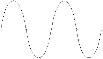
Notice the bends where the wave crosses the zero line. Class AB makes up for this by causing the tubes to conduct a little bit more of the cycle so as to overlap the cut off to turn on times. In other words, those bends are now in the signal past the zero crossing. The result is a "purer" sine wave. The resulting spikes can then be filtered out with a small value capacitor that will not affect the audible high frequencies. Inverted feedback will also reduce this "crossover distortion". Also eliminated is the low volume level distorted sound of the crossover problem in pure class B operation. In essence, the tubes conduct as class A for low level signals, and as class B on loud level signals.
The real audible difference in a push-pull configuration, even in class A push-pull, is the fact of reduced even order harmonics. Or, increased odd order harmonics. Whichever textbook you wish to refer to, the fact is that odd order harmonics dominate in the push-pull stage. This is where the real sonic differences between push-pull and single ended amplifiers occur. This is not to imply that the crossover distortion is not real, just that the distortion is virtually eliminated by biasing and filtering. Transformers, too, naturally filter out the spikes. Solid state amps don't have transformers to do this, so many persons complain about the buzz, grainy or raspy sound they hear. It is actually the crossover spikes they are listening to. It could also be a higher amplitude high end which causes the high end to sound (subjectively speaking) like an icing on cake, and not the cake itself, which is what we want to hear. Better amps usually use a small choke in line with the output to the speaker to reduce the spikes that NFB doesn't. OTL (output transformer less) tube amps usually work in class A anyway so there is no problem with cross-over distortion there either.
In many high end tube amplifiers there are two potentiometers per channel that are user accessible. They are labeled "bias". These potentiometers are there to set the bias for the output tubes so that they match each other. This allows both tubes to amplify their respective half of the signal equally. This also causes the tubes to cancel the even order harmonics (or whatever). Many audiophiles mis-align the biasing. They claim that the amp sounds better. What is really happening is that now even order harmonics are showing up because of not being as canceled out by the push pull configuration.
A word of caution, though. Mis-biasing can cause one or both of the tubes to conduct too much and they may overheat. This will be indicated by a nice looking cherry red plate. The tube life will be reduced dramatically. So caution is to be exercised when changing the bias adjustment. Even if the sound gets better and better, the need to change the tubes becomes more and more often. It is close to becoming a class A push pull amplifier.
Considering the fact that 90 percent of an amplifier is class A (the preamp and driver circuits), there should be little if any benefit or lack thereof in sonic quality between the two typical output biasing schemes. The power gain and efficiency of push-pull, however, is an intriguing fact. But the even harmonic characteristic typical of tubes is still preserved even through the push-pull scheme. Russel Hamm showed this to be true in his paper (Tubes Versus Transistors, 1972). I believe that this is more due to the driver tubes, generally triodes, and the transformer itself, since they make the even order harmonic distortions.
On the other hand, as my experiment with a single ended amp design proves to me, one has to wonder if there is really an advantage of an 18 watt per channel amp over a 5 or 6 watt per channel SE, when the SE amp drives my high end low efficiency 8 ohm speakers better and cleaner than the 18 WPC P-P, where the SE uses cheap transformers rated for 4 ohm speakers and the P-P uses better quality tapped for 8 and 16 ohm speakers!
Oh well, all for the love of music!
Back Home
Back to EZIndex