This has been a project that I had been working on for about two years now. Due to the person who I am working on this for and my time we had to let it take this long. We both have very busy schedules and are about 300 miles apart.
This amplifier incorporates the design I call the solid state tube. I call it that because the combination of the two types of solid state component sounds very close to tubes without the so-called soft clipping or compression techniques many engineers use to try to make the transistor sound like a tube.
The design is based on what I used to call alternate interleaving, where every other transistor is the alternate type. In other words, I use bipolars and FETs in such a way that the circuit has an FET then a bipolar then an FET-bipolar-FET, etc. What I do here is to take adantage of the best properties of both components, while minimizing the flaws of each at the same time.
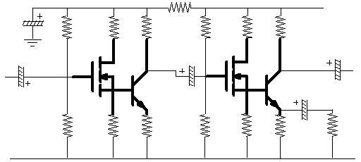
Here is an example:
Yup, each stage is what I have illustrated on my home page. The FET's desirable qualities are the relatively infinite input impedance, and its negative temperature coefficient. This means that if current increases within the channel of the FET, it produces a negative voltage at the gate. This causes the gate to reduce the current in the channel. No thermal runaway. I then tie the source output (I make almost all the FET's source followers) directly to the base of a bipolar transistor. The bipolar transistor has the desirable qualities of requiring a very small turn on voltage, a very high gain, and very much flexibility as an active electronic device. Both have the desirable quality of low power needs and longevity.
Undesirable qualities of the FET are the relatively high input capacitance, a high voltage turn on requirement (from 0.5 to 4 volts or more), low power/voltage for small signal types (I can get small signal bipolars up to 1 or 2 watt. FET's only up to 750 milliwatts), and limited variety (mostly N channel available where I could use some P channel's). The undesirable qualities of bipolars are base current, low input impedance, and thermal runaway due to both inherent heat properties of silicon and the phenomenon called the Early effect (AKA base width modulation) and base current recombination. The input capacitances (Miller and shunt capacitances) are also there and variable due to the aforementioned Early effect.
The input capacitance of the FET is virtually eliminated by the use of direct coupling the bipolar at the source output. This, according to a couple of references, is known as a cascaded connection. It can also be looked at as a Darlington connection (Darlington invented the connection of two or more transistors from emitter to base to make it a current amplifier. It makes for a very high gain amplifier). In essence, any high frequency content from the FET that would normally be shunted by the input capacitance hence reducing gain, would instead be passed on to the bipolar transistor. Since the source follower is virtually a unity gain (a gain of x1) amplifier, this makes for a very wide bandwidth at unity.
The bipolar transistor's input is now more controlled by the signal than would be previously realized. This is because the output of the source of the FET is now in phase. That is, the voltage signal and the current signal are in phase. This is significant when one notices that if the voltage and current were not in phase, say by 180 degrees, then as the signal voltage went positive, the base current would also go positive, because the bipolar is now conducting more, but the base current will be out of phase with the signal current, so cancellation will be the result. Some may argue that this is what makes the impedance of the input, but when considering that music is composed of multiple frequencies at various amplitudes, the effect of a particular voltage level, considering base width modulation, changes the characteristic of the transistor at that moment (the transistor's amplification factor, or beta, is the result of the base layer thickness. Base width modulation causes the effective base region to widen or narrow. So its gain decreases or increases, respectively). So any other signal that happens to be there at the same time will not be amplified the same way as at others. This is a form of distortion that is currently unmeasurable and does not exist as such in vacuum tubes inasmuch as they do not have a variable input current under typical operation. FET's also do not display this effect.
Now, with that said, the FET's output will be of sufficient current size so as to overpower, or match the base current, so that there is no destructive interference with the signal as opposed to degenerative feedback. The input of the FET is such that it merely reacts to the signal of the previous stage and not interfere with it the way the base of a bipolar would. So we can say bye bye to the effect of base width modulation and to thermal runaway. Thermal runaway causes base current to increase as well since current is increasing from emitter to collector. So since the base current is flowing through the FET channel, the FET's inherent response is to reduce its current, because the sourcce voltage increases, and the gate reflects this as a more negative voltage, bringing the device closer to cut off, or reducing the channel current. This in effect stops the bipolar from running away. The result is a very stable stage.
What I mean by destructive interfrence is that because of the phenomenon called the Early effect, or base width modulation, feedback current can alter the input signal, not just lower the amplitude of it. A complex signal as you may already know is made up of many frequencies. The Early effect is based on voltage level and frequency 9higher than audio, that is). The fundamental is generally the highest in amplitude. So the fundamental will get feedback more than the higher frequencies. That is, the higher frequencies will get propotionally less feedback (except after a certain frequency where Miller capacitance starts to cause high frequency roll off). So, if the fundamental gets about 10% feedback the higher frequencies may only get 7% or less (arbitrary numbers, just for example). This causes an imbalance of harmonic amplitudes. Our hearing is most sensitive to changes in the amplitudes of harmonics.
HARMONICS IN THE SOLID STATE TUBE
When all is said and done, the overall affect of doing this combination is that the signal gets stronger even order harmonics from the FET (it is said that FET's make stronger even order harmonics before clipping) operating within its more linear region, not going into clipping. The BJT amplifies this signal with its stronger even order components from the FET. Since the second harmonic is strongest, it gets amplified by the BJT also. So the odd order harmonic is overpowered by this (someone once told me that I "flooded" the amp with even order harmonics. Well, OK. Take a look at what I think about harmonics here). The result is clipping with a strong second harmonic component. Can you say triode?
While a tube can tend to be warmer overall, when designed properly what one should have is a true natural sound. I have heard tube amps that do this. This combinaiton of solid state components is warmer than BJTs or even FETs by themselves, but not quite as much as the tube. However, it does have a natural, true sound quality, which is what, as a purist, our goal should be.
APPLYING IT
I had come across a site, while searching for tube sites, of a gentleman who makes tube microphone amplifiers for recording studios. On his site he has some papers. In one of them he speaks of how he tried many experiments which led him to conclude that there was more to the difference in sound quality than what had been established. I wrote him with my proposal and belief of what the difference was and to make a solid state amp for him using my design concept. He agreed. I made the first prototype and according to the tests (he has yet to actually hear it, which I believe will convince him to use this design) the harmonic levels were just like his amplifier, except I did not use NFB and the distortion was 3%.
The first problem I had was matching impedances. I was being overzealous with trying to use orange drop caps instead of electrolytics, which I would normally use. The second problem was having a balanced input and output. The third was noise. The fourth was gain. It was only about 35dB.
Well, my second prototype used NFB, was balanced, and had better impedance matching. But the noise was still there. The distortion went down to about 0.1%, and the harmonic balance was still the same (strong second harmonic). However, the noise level was still high. Gain was more at about 45dB. He required 60dB, or a voltage gain of 1000.
The thing I did was to differential
the stages to get balanced input and output. Doing this, however, made
for a stage gain that was very high. This is because since current cancels
at the junction of the emitters, the gain of that stage is Rc/re, or the
collector resistor divided by the internal emitter resistance. So my stage
had a gain of 4700/25 or 188. I later realized that if I used a resistor
between the emitter and the junction, then gain would be Rc/Re+re or collector
resistor divided by emitter resistor plus internal emitter resistance.
This will be applied in my third prototype. This is what a stage will look
like:
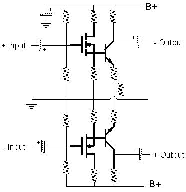
The outputs are inverted versions of the inputs, that is why put minus on top and plus on the bottom. Notice the emitter circuit. There is a resistor coming from it to another resistor to ground. This resistor can be used to limit the gain of that stage by means of local degenerative feedback. This also lowers distortion somewhat. Also notice that I am using a single ended power supply. I am also going to use another local NFB loop reducing the gain further to about 10. This way I can have three stages amplifying 11X11X11 for a total gain of 1331. More than enough, I would say. I will have a level control after the first stage.
Notice too that I am using electrolytics and interstage capacitors as opposed to direct coupling. One would think that I would have a phase problem. However, it has been measured to only have about a 5 degree maximum phase shift. I attribute this to the fact that the gate of the FET only cares about the voltage portion of the signal, and it in turn feeds the BJT with a signal that had both voltage and current phases at 0 degrees. So phase shift should be minimal. I guess I was on the mark with that prediction. Therefore there should not be a problem with using any kind of capacitor, except for the internal inductive properties. Also, I have calculated that I can use low value (under 1 microfarads) capacitors, so elimination of electrolytics can be done.
Another thing I realized was that he used three amplification stages and a fourth buffer stage (a follower to match output impedance). This means that I can make my amp with three amplification stages also, each with a gain of 11. This way noise wil be virtually non existent, and I get the overall gain of 1000 (60 dB) using local and not global feedback. To me, the best of both worlds.
The noise level will be low because each stage will not contribute as much as if I had the gain of each stage more than a certain level. It is a matter of making the noise floor as low as possible. Let's say I had not used the emitter resistor. The gain will be 188. This high a gain comes with two things in this particular circuit (differential), high noise and a high frequency response that is peaky. That is, the highs are louder than the lower frequencies. So the amplification level of the high frequencies is more than the calculated 188. And with no signal what the amplifier has available to amplify is noise. This is because this connection minimizes Miller capacitance effect, which is good but bad. The resistor degenerates the amplificaiton level so that 1) we get less noise and 2) we reintroduce some of that Miller capacitance to bring the high frequencies within more respectable and acceptable levels. So now we have some roll off. This is OK because the local NFB loop will bring back the highs in a sense because it will lower the level of amplification of the overall frequency response to be equal with the lowered high frequencies. So now we have a flat response beyond the audible range. My second prototype, without NFB was about 30 to 15000 Hz. After it was 5 to 60000 Hz.
Now, the noise level is low. We put in a signal of one volt and get a signal out of 11 volts. The next stage has the same low noise level. But now we are putting in an 11 volt sgnal. So SN ratio is even better there. The output will be 121 volts with the same noise floor. The third stage takes us to the stratosphere with a signal out of 1331 volts. Of course, the amp is severely clipping at the second stage so realistically we have our level control down. Also, we are putting in a signal that has an average of 20-50 millivolts anyway, with maybe 1 volt peaks. But this is OK too, because our first stage can handle this with no clipping, and the level control should be down to the point where there will be no clipping or minimal clipping out anyway. This makes me wonder why one would want an amp that amplifies so much to begin with, but, it's what is required.
When this amp is driven into clipping, since the FET has the strong second harmonic, the bipolar will clip the fundmental and the second harmonic in kind, maintaining the level, so the result should be similar to clipping a triode.
Input impedance is matched with resistors. That is, I use a couple of capacitors first, connected to 1500 ohm resistors which go to ground, then another set of capacitors go to the gates of the FET's. I need the first set of capacitors to isolate the phantom voltage from shunting to ground through the resistors. The output impedance is set by the source resistors and the output capacitors at 600 ohms. It puts out about 1.2 watts. I was actually able to drive a speaker with it.
Now, the output of this amp is two separate source followers. I am using MOSFETs in the output to make sure I am matching output impedances. I have my reservations about the emitter of the BJT being true low output impedance in spite of the math. The channel of the output MOSFETs has an on resistance of 0.5 to 10 ohms. To me that is a true low output impedance. I am not going to use any NFB at that stage. Is allows me to have some more even order harmonics. Since I have been told that a follower output will have about 10% of the distortion of the amplified output, this will give me about 0.2 to 0.3% even order distortion components. OK, it will sweeten up the sound a little, but that is OK if we want that tubelike sound from transistors. 0.3% is not too shabby. The aforementioned tube mike amp has a distortion of 0.2% but it gets rave reviews.
THE PROJECT
I have the design and the components ready to go. I just now need time to assemble it. The power supply is another tricky thing, since I need about 70 volts or so and need a goodly amount of current in order to have the (theoretical) 4 watts output from a class A amp. (I likely need 11 watts of power supply to acheive this. At 600 ohms it idles at 160 milliamps). I actually get about 1.2 watts from this amp. To get the theoretical 4 watts at 600 ohms requires about a 140 volt power supply. I am not going to do this for a prototype.
I am going to use a 25 volt 2 amp power transformer from Radio Shack and a voltage doubler. The peak voltage of it is about 35 volts. A full wave doubler will give me 70 volts. I use plenty of filtering in order to make sure I have little ripple. I also have a voltage regulator of 68 volts for the gain stages and for the phantom 47 volts. So, 70 volts at about 1 amp should provide sufficient power for the output.
More to come.