OK, I know, "Transistors sounding like tubes? Aw, come on, Gabe, it's been tried before but no such animal", but if I were to tell you that this amp had the harmonic characteristics of tubes without fancy feedback tricks, what would you say?
Yet, that is exactly what I have here. This is what I call the solid state tube.
THEORY OF OPERATION
First, I would like to discuss the reason why this circuit does what it does. As many who are reading this page know, tubes sound the way they do because they "make" primarily even order harmonics. However, from reading my other pages, you will note that I do not subscribe to the thought that an active device like this "makes" any kind of anything. A device has to be an oscillator to make any kind of wave.
On the other hand, the thing that the tube does do is, when not configured linearly, is to make a sine wave asymmetrical. It does this because the space between the curves as seen on the plate characteristics chart displays a variation between the lines of voltage per current levels. So the original sine wave is misshapen into what any good follow-the-book-to-the-letter student of physics would call "harmonic distortion". This is because the resulting wave could be defined as having harmonics of varying phase and amplitudes. However, the reality is that the wave just has a different shape. Nothing more. These harmonics have not actually been "made" (The Science of Music).
Yet, the only thing this allows the tube to do is make the sound seem both louder and closer to the ear. This is because our ears actually do the same thing, due to the pressure differences on either side of the eardrum (one side air, the other side fluid). Our ears tend to misshape the sine wave. So tube amplifiers tend to have more imaging and spacial sonic character than their solid state counterparts.
The sonic signature of the tube, however, the "warmth", as it were, is more likely due to two things; high input impedance and shunt input capacitance. The input impedance of a tube is many megohms. This coupled with a shunt capacitance of anywhere from 2 to 200 picofarads means that the device starts to roll off in amplification response low in the audio range. This can easily be demonstrated by biasing the tube in two different areas.
A tube, let's say the 12AX7, is biased with a current of 0.5 milliamps. The sound will be fat sounding. This is as if one had an equalizer and boosted the response around 100 to 300 hertz a few decibels. Bias the same tube at about 1.5 milliamps, and because of the lower internal impedances, the response will be very noticably less "fat" sounding. The same kind of effect can be had by using a 1 megohm resistor at the grid versus a 100k resistor.
So the tube had both of these things in its favor. We like the sound because it is mellower, and easier for the ear to listen to because of the asymmetrical wave shape, which mimicks our hearing.
The bipolar junction transistor (BJT), on the other hand, has a very low internal impedance. So there is little to no interaction with shunt capacitance. Of course, the capacitance causes similar phase shift problems, but that does not affect the frequencies we are dealing with as much, so it is not as relevant. So the warm sound one experiences from tubes is gone. That coupled with the fact that it is easier to make a transistor amplifier with extremely low distortion characteristics makes for the sterile, hard, listener fatigue experience one gets with pretty much all solid state equipment.
The BJT also has a characteristic that tubes are pretty much immune to, namely base current. There is a tube "trickle" current at the grid, but it is miniscule and virtually nonexistent by comparison to the BJT. However, the BJT, and in particular the ones used in most audio applications, have base currents on the order of 0.5% to 10% of the output current. This current is not fixed either. It varies with the signal, increasing as the input voltage increases, and decreases nonlinearly with the low input level.
Now I am not talking about overall volume level of the signal, but the variation of a single sine wave. So peaks that may occur naturally from an instrument is compressed by the BJT. That is correct, the solid state amplifier compresses the signal, not the tube amplifier, as many claim.
In comes the FET. The field effect transistor has an interesting characteristic. The input impedance is very much like tubes in that it has a ten trillion ohm input impedance. That with the shunt capacitance allows it to have a similar "boost" affect to tubes. The output impedance though is very low. I do not know why yet, but an amplifier made exclusively with FET's, while sounding very good, does not quite sound like a tube as some claim.
However, if one considers the idea that if one takes the best characteristics of both devices, and combines them in some way, the result might be astounding.
So we take the input charateristic of the FET, and combine it with the high amplification ability and ease of design, and light weight, and low power consumption of BJTs, and hope for the best. I used the FET as a follower/impedance bridge. I connected the BJT base directly to the source of the FET.
What happens here is that the phase of voltage output versus current is zero. In other words the voltage and current waves are in phase. Since the base current is out of phase with the voltage at the base, this tends to cancel out the affect of the base current fed back. So the net result is a voltage and current phase relationship that is zero. There is now no internal NFB to distort the signal in the BJT. Also, the affect of Miller capacitance in the FET is gone, because of using it as a follower. Now, the BJT amplifies the characteristics of the FET.
The result? Astonishing sound. Gone is the fatigue and harshness of transistor amplifiers. In is the warmth, imaging and punch of tube amplifiers.
I have analyzed the amplifier with a spectrum alalyzer (a friend did it) and by just looking at it on my ole scope. The result was a distortion pattern like a triode tube amplifier. Strong second harmonic, lesser third, and so on. The wave out looked fine at lower level, but when amplitude was increased the asymmetry that one sees in a tube amplifier shows its head, and the clipping is even "softer".
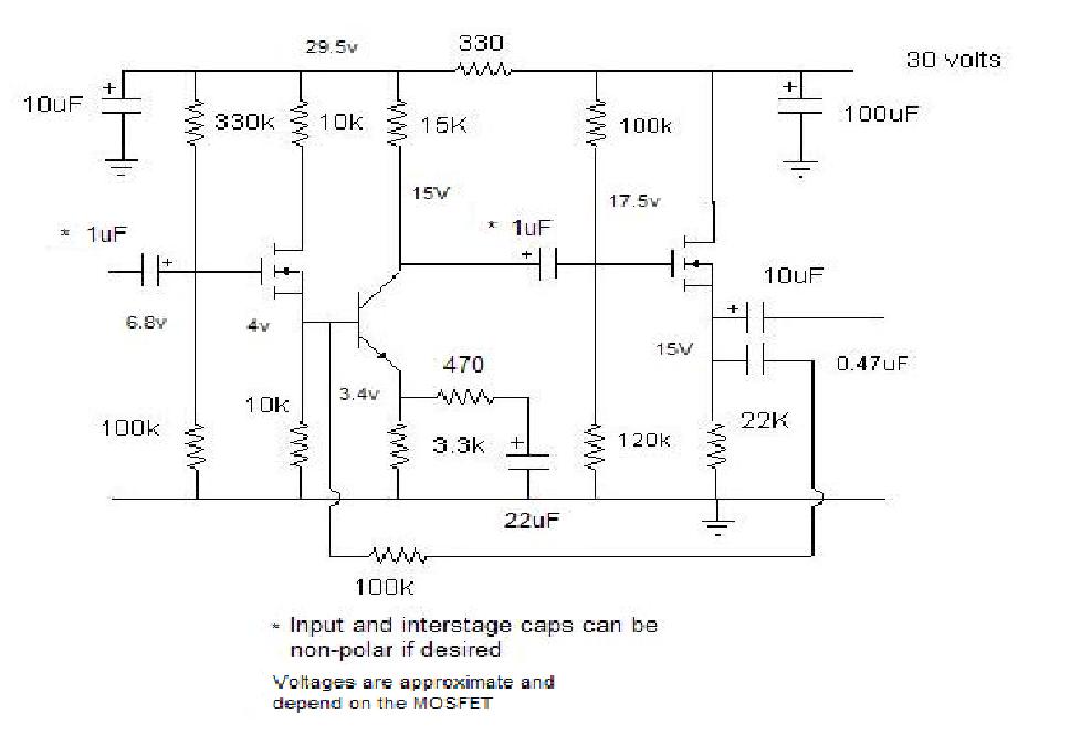
BUILDING YOUR OWN
Here
is the schematic of my much improved circuit.
This is fifth generation. The first generation used a JFET and no NFB, The second used a JFET and a high beta BJT. This is a BJT with one of the lowest base currents available. The third used a MOSFET. The fourth was the first with NFB. However the NFB loop, while cleaning up the sound a bit, made the input impedance dynamic and low. I did not want this. This final circuit puts the NFB within the circuit only affecting output imedance by lowering it even more.
This was the holy grail of NFB applications, because it cleaned the sound up extremely. It also made the wave output more tubelike, and clips softer. Mind you, this is just a regular old application of NFB. And a very small amount at that.
The frequency response of this amplifier is flat from 5 to 600kHz, at least. My function generator tends to roll off starting at that point up to 1Mhz. Yet the sound does not sound like it goes that high. Distortion is about 0.05%.
Yet the sound is so clean, so imagey, so warm that it is amazing. As one person put it, "you hear more of the music". It is as clean as any tube amplifier. And almost as warm (one can make a tube amp sound very warm). The input allows for a wide variety of connections, and it does not load the output of sources. The output impedance is so low that it can couple to any amplifier.
Experiment with the value of the NFB resistor for best results to your taste. If you use a different power voltage, adjust the resistances accordingly. But the 330 ohm for the bypass circuit of the BJT should remain the same. The devices can be any small signal MOSFET with a transconductance of 10,000 or more, and a BJT with a beta of 150 or more. I use the BS170 MOSFET and the NTE-123, both from NTE electronics.
The amplifier as a unit can be used as a stage in a phono preamp. Use two or three stages for RIAA equalization (one of my design coming soon).
I hope
you enjoy it as much as I and a few friends have. Let me know!