As I had mentioned elswhere on these pages, my first love in electronics is tubes. I collect and restore antique tube radios, I have made tube amplifiers, and prefer their sound over solid state equipment. However my knowledge is not as deep in tubes as I would like, but it is growing in leaps and bounds.
Knowing about solid state electronics, it has always baffled me that the tube could sound so different than the transistor. I once had a contempt for the argument for harmonic distortion properties of the two devices, but that has now been changed. Why the two devices made their respective harmonic distortion properties was a mystery to me. But it has also now changed, to a degree.
It would seem that the transfer and output (plate, collector and drain for tube, bipolar and fet's respectively) curves determine the harmonic pattern. In my paper Harmonic Distortion I discuss what actually happens to a sine wave as it passes through an amplifier and how the so called harmonic distortion is determined. It would seem though that the transistor and the FET (and the pentode for that matter) would give the more linear performance, based on the transfer and output curves. But they don't. One would think that the sine wave would be more close to the original. But it isn't. The harmonic distoritons when analyzed reveal a strong odd harmonic content.
So how does this
happen? What makes the odd harmonics to be stronger? If we take a look
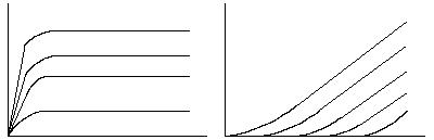
at the curve for the pentode (which is very close to the bipolar and FET)
we will notice something very interesting.
Do we see what it is? It is speed! If we made a plot or graph of how quickly the device turns on, we will see that the device (pentode, bipolar and fet) turns on faster than the triode. This is determined by the fact that the line starts by virtually going straight up, or more accurately at an angle greater than 45 degrees. Viewing the curves for the triode reveals that the angles for the rise in current (for the first few volts. The rest of the curve goes beyond 45 degrees) for voltage are under 45 degrees. It takes the triode longer to reach full output. Let us make an important note here: we are discussing audio related components. There are some triodes that can be driven such that the angle is greater than 45 drgrees, but they are for RF and other special purposes and never used in audio. I am not saying that the 45 degrees is significant, but the rate of turn on is.
In fact, Steve Bench has done some intrigueing experiments on direct heated triodes where he "starved" the heaters by running them at 3.5 volts instead of 5 volts. The results were curves that started going greater than 45 degrees. The distortion was lower.
How does this relate to the harmonic content? I have yet to discover this. I surmise that the speed of turn on is related to the sharpness of the square wave, hence the Fourier analyzed odd order harmonic content. Picture this: If I have a device that turns on quickly, the graph of turn on to full voltage versus time would, in an ideal situation, reveal a line drawn straight up, then straigh to the right, if the y axis was the voltage and the x axis was time.
So what is the solid state solution? There have been attempts to make the transistor sound like the tube at clipping (I do not agree that the SS amp sounds as good as the tube amp even with all specs being good). From using a diode as a clipping device to digital synthesis. But they just don't woik (sorry, a bit of the ole Brooklyn accent getting in the way there). So what can be done?
It is said that the FET is the closest device to sounding like a tube there is. But I have tried FET only circuits and they do sound good but not quite as close as the claims made.
However, there is a combination of solid state devices that comes closest ever to the triode. It is what I affectionately call the "Solid State Tube".
The Solid State Tube is a combination FET and Bipolar transistor device that takes advantage of the properties of both devices. It is by no means an original concept, nor by any means not used. A form of it is used in BI-FET op amps. Some high end audio manufacturers also use FETs in the input of their amps as well. The thing unique about how I employ it, though, is that I treat the combination as one device. So instead of merely front ending an amplifier with FETs, I incorporate them throughout. I used to call it alternate-interleave. Figure 2 is an example.
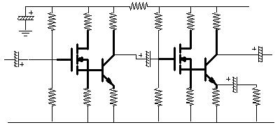
As you may recognize,
this is the circuit that is on my home page next to the triode. I did that
(on my home page) because I believe that this combination has a very similar
sound quality and harmonic pattern as the triode. I highlighted the combination
in each instance to show how I treat it as a single transistor, as opposed
to two. Imagine it as a tetrode, where there are actually three active
electrodes, if you will. The gate, the emitter and collector. The source
of the fet and the base of the bipolar are in theory connected together
internally. The connection of the resistor to ground is for bias only.
The resistor at the drain is also for bias stability. Input for this device
should only be allowed to the gate or the emitter, and output from the
collector or the emitter only.
Without
actual test equipment analysis (coming soon) I would guess that the characteristic
curves of the MOSFET are the same for the source output as for the drain
output but at a smaller and inverted form. This inverted form combines
with the bipolar. Amlified by the bipolar it combines with the non-inverted
curves of the bipolar. This would tend to cancel it out. Or result in a
different curve. FFT analysis showed that the open loop distortion was
strong second, lesser third, then fourth, etc. So I could only guess that
the curves are more like the triode.
More coming soon.
Gabe Velez