This project I have been puttig off for a long time because I figured my preamps were doing plenty for the sound quality of my systems (and others' systems) by themselves. But since my recent purchase and projects with Single Ended versus Push Pull tube amps, I figured I would give my circuit a try in a power amp.
Below are two versions of a power amp that I will build (that is, when I decide which one I will build it). The first is a simplified version that takes advantage of the thoughts I have about the combination. The second more closely resembles what I think should produce the sound I want, namely tubes. I know, "why not just make a tube amp?" Because it is cheaper and more efficient this way! Besides, I already did make a tube amp!
I am going to strictly use push pull because I really do not want to make such huge brute force power supplies and use large heat sinks. It seems that the more things change the more they remain the same as regards getting SE class A amps to work. SS ones get very hot, like tubes!
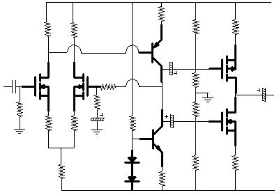
Here is the first version of amplifier using my ideas about alternating the two types of transistor:
It looks like so many bifet op-amps that use FET front ends, or outputs. Here I use bipolars as the driver/current source circuit. The input diff gets feedback from this combo as opposed to the finals because I wanted to keep the outputs isolated via the caps from the rest of the circuit. Why? For simplicity's sake. Besides, I do not subscribe to the arguments for or against direct coupling.
I am going to use regulation (not shown) to provide biasing to the voltage dividers to the final FETs so as to keep them stable. Fortunately, with their negative temperature coefficient, I can do this with little fear of blowing them out due to overheating. Also, I am using them to amplify signal, too, to have a near rail-to-rail output (that is, whatever the rail voltage is minus the drop across the 1 ohm). The outputs will be biased at just above cut off, which should have them idle at about 40 milliwatts, assuming a 1 ohm source resistor with a drop of .2 volts (0.2Vx0.2A=0.04mW). I will include an AC feedback for better linearity and distortion ratings, but first I will listen to it as is.
I actually used the diff/driver circuit in a preamp and the sound was high end strong. The odd thing about it was that the amp I hooked it up to had current limiting which went on when the highs were particularly strong (it was a Bose system so it was already contoured for high and low end boost). Wild, I usually have the opposite occur, where the bass is too strong. However, the sound as ok and clear. I attribute this to the Miller effect reduction in the differential pair. However, I did not have the source resistors in that prototype. I did another amp with the resistors and the high end smoothed out a bit. Not harsh.
I am counting on the capacitance of the power MOSFETS to help reduce the high end harshness. Using them also for their even harmonic content should help make it a nice sweet sounding amp. The signal to each of them is taken from the same place. This is because being a complimentary pair there is no need for phase inversion. Each transistor will conduct only that portion of the wave that brings it into conduction. They will be biased AB, so crossover distortion should be low.
I am only going to make this about 20-30 watts.
More to come!