This is a three band AM and Shortwave radio covering the frequencies from 550 Kilohertz to 18 Megahertz contiguous. This means that band A is from 550 KHz to 1750 KHz, band B is from 1650 KHz to 5.5 MHz, and band C is from 5.5 MHz to 18 MHz. The band indicator however has a D on it also, signifying that RCA used this same mechanism for a four band version. In fact, they also made a five band version. The schematic indicates that there was also a version of this chassis that went with a record player.
It is rare to find a shortwave radio that covers from 1.7 to 5.5 Megahertz. I was delighted that this one did. My Zenith Transoceanic is one of the only other ones I know of that does (the last model they made. Sorry Transoceanic fans. I do have a fifties model, not the 500, coming soon.)
The tube compliment is a 6A7, two 6D6's, a 6B7, a 41 and an 80. The circuit is a TRF/Superheterodyne. I think that this is the best combination for this kind of application. It allows for both superior sensitivity and selectivity. The only other design I favor is the superheterodyne with separate front end RF amp and local oscilator tube/transistor as opposed to composite mixer. It has a 10 inch dynamic speaker. Unfortunately my 7 year old got to it when he was two. I need to find a place that could recone it. The spider and coil are still intact. I am currently using a PM speaker in its place while still using the electromagnet coil as a choke for the power supply.
I got this beauty at an auction warehouse. They had an open house before the auctions where a person could go in and purchase pieces before being auctioned away. I picked it up for $60 U.S. It had a bad 6A7 pentagrid converter, so I substituted a 6BE6 pentagrid miniature. It id not work at first. So, without a schematic I had to rewire it so that the oscillator part would oscillate. I took the 6A7 tube apart in order to follow its connections and found that where the first grid was seemed to be just two rods in the electron stream. So I figured that the circuit was designed to use this as a "tickler" to cause the tube to oscillate.
I now know that I am wrong, at least from the way the schematic reads. At any rate the thing works great and have left it as is since. I have had this one for nine years now.
Since moving to Richmond, Va. though, I met a fellow who restored the cabinet for me. He did an outstanding job.
I am currently in the process of replacing the capacitors in the audio circuit. I have replaced the power supply caps and two of the audio caps and the sound cleared up nicely. I then decided to do all of them. There are two boards in there that hold many of the resistors used in the circuit. I decided to leave the resistors alone because they are rounded out values (20K, 300K, 40K, and the like) and they are real cute. The body color is the first value, followed by two dots of color for the multiplier. I would hate to replace them with the peculiar values we use today because it may change the quality and performenace of the circuitry too much. But the caps sure look dead.
Here are some pics:
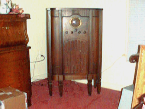
This is the complete radio. I wasn't aware of the many sources for speaker
grill cloth at the time it was redone so I used what I could find from a fabric store.
I had my friend use a semi-gloss finish. I think it really looks beautiful. This picture
does it no justice.
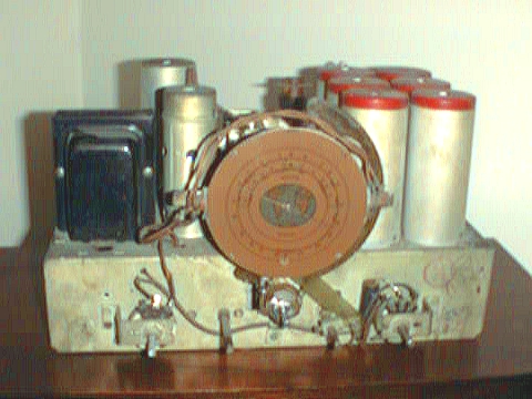
This is the chassis. I did not do much to clean it up and make it shiny because I wanted to keep some semblance of the antique look. I did the same for the label ring around the dial. I polished it a little leaving some of the varnish for that antique look.
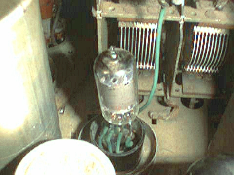
This is the "modification" I did to get the thing to work. At the time
again I had no idea of the sources available. I met one guy who would have
robbed me had I used him. He had a 6A7 for about $100. I can get
one new for about $15, or used for $3.50 from Antique Electronic Supply.
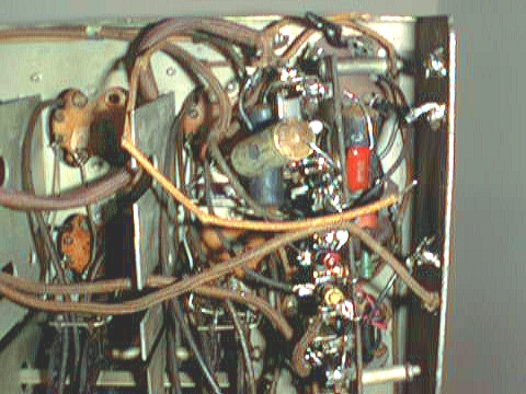
This is the work I am currently undertaking. I have a basket full of NOS caps that I used, and as you can see I am using "orange drop" caps where I do not have exact values of NOS. See the pretty colors of the resistors? Thanks to Nostalgia Air having the schematic this job is tons easier.
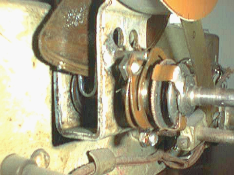
This is the tuning mechanism. It is ingenious in that when fully depressed
(shown) the tuning is gross, and when pulled out the tuning is fine. This
allows for tuning of the closely spaced shortwave stations. I took it apart
while cleaning it and kinda screwed it up, so I am on the lookout for another
one. It works, but the plate that it friction rolls against is not true (flat)
anymore and tuning at some locations when using the fine tuning does not remain
on station. Also the friction is lost when it is in for gross tuning, so it is
more difficult to tune. Notice the brass tab on the upper part of the tuning
shaft where it meets the "gear"? While trying to add tension to it I broke it,
so I had to solder it back on, hence the hard tuning.
UPDATE 1/20/1999 - I have recapped the amplifier section, the power supply, and one stage of IF. The sound is SO much better. I actually get a nice clean high end! Bass is full and clean. It is almost Hi-Fi sounding. The reception has also improved greatly, likely due to better AVC control. I have put the chassis back in the cabinet for now. I need to acquire a couple of rubber spacers for the chassis to rest on so as to align the dial and shafts in the holes. The original rubber was far too damaged to reuse. I also may need rubber grommets for the tuning cap.
More to come!