Power supply design is no real big deal. One could make a career, though, in power supply design and implementation. This is because some high tech applications require so many things like failsafes and regulation and multiple voltage and current outputs. But for the purposes of a good audio amp, there comes a time where you reach the so called point of diminishing returns. In other words, where does the economy end and the benefit begin, or when am I at a point where there just can be no more improvement? I will leave that one to your own opinion.
We will first discuss the different types of power supplies and the roles they play and then give the necessary directions on how to make one to adequately supply our audio needs.
But first, as on my home page I offer this warning: Tube circuitry employs dangerously high voltages. Never work on a circuit while it is powered up, except to read voltages and signals with well insulated meter probes. Always wait for the circuit to fully drain before working on it when power is removed. Make up a "bleeder" circuit using a 100K 2 watt resistor with insulated alligator clips at either end (with some wire attached. Use electrical tape to insulate the bare wires) so you can drain power supply capacitors fully, since these can still store some electricity or regain it due to a phenomenon called soakage. Simply clip one end to ground and the other end to the positivve terminal of the capacitor, or one end to negative and the other to positive. Voltage levels from 25 volts and up can be lethal. I mean, you can DIE from it. PLEASE be careful.
THE DIFFERENT POWER SUPPLY SCHEMES
There are basically two types of power supply schemes. But the funny thing is that both are really much the same with the exception of efficiency. The first is the brute force power supply. The second is the switched power supply.
The Brute Force power supply gives all of the power available all at once. In other words it builds a huge store of reserves which a circuit can make use of. One of the drawbacks of this kind of supply is the need for large transformers and large capacitors. Actually, there are only two reasons these are drawbacks. The first is that the components are costly, and the second is that they are bulky.
Enter the switched power supply. What this does is takes the line voltage (110 AC) and converts it into a high frequency pulsed voltage. One of the reasons the brute force power supply needs such large capacitors is that the frequency of the DC is low. When the AC which is at 60 hertz is rectified into DC, it becomes a 60 or 120 hertz pulsing DC which needs large value capacitors to filter. With a switching power supply, the 120 hertz DC is converted to a 40 or higher kilohertz DC by a circuit that doesn't care about power supply ripple (the 120 hertz pulses). With 40 or higher kilohertz one does not need such large value capacitors to store the electricity and filter the ripple, or pulses. So the circuit can be made cheaper (by not using a bulky, costly power transformer) albeit more complicated.
Oh, yeah, by the way, there is a direct connection to the AC line. So, those who scoff at using the AC directly without an isolation, well, don't open up your computer or TV or most other electronic devices these days. There is NO isolation in them. I know, I blew out a TV and a fuse once because I was not careful about grounding. If it had an isolation transformer like they used to have I would have only blown out the TV.
Anyway, our only dilemma here now is which power supply do we use? I personally, for the sake of simplicity, choose the brute force power supply. This is what we will design and build here.
HOW TO BE BRUTAL
First we need to know what it looks like in a schematic. It is very simple. A power transformer is chosen that will provide a couple of things, depending on what kind of rectifier we will use. Many tube audiophiles believe that the tube rectifier is the only way to go for tube amplifiers. Some claim that if you use a solid state rectifier you make the amp a solid state amp. I suppose then that, since tubes originally were made for use with chemical battery power sources, they were chemical amplifiers? Not at all.
The goal of a good power supply is to provide a constant voltage with no noise, ripple, and a relatively unlimited supply of current. No more, no less. It should have absolutely nothing to do with the quality of the sound of your amplifier. Nothing. A good power supply should be transparent. If your amplifier sounds great with a tube rectifier, then it should sound just as great with a solid state amplifier. If it doesn't, then the power supply sucks. Or perhaps the amplifier does. Simple as that.
Now, to get off my soap box and on to circuit design. I will cover both tube and solid state rectifier design here. You decide which will be best for you.
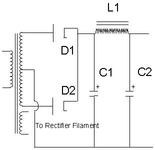
From the circuit below you see a transformer, a tube double diode, three filter capacitors and a choke coil. This is the best form of brute force power supply. The choke and capacitor combination (called a pi filter because the capacitors and choke look like the greek letter pi) reduce any ripple to virtually nothing. The power transformer in this example is a center tapped 300 volt with a 5 volt filament winding for the rectifier and a 6.3 volt winding for the filament of the tubes used in the amplifier. The center tap does not divide the 300 volts. Instead it is from the center tap, three hundred volts to either end. So it is actually 600 volts. But the connection to the rectifier causes it to be 300 volts.
PARTS LIST:
117 volt to 300-0-300 volt 150 mA power transformer with 5 volt filament.
D1,2=5AR4 or (as below schematic)5Y3GT rectifier tube
3-5 Henries choke
C1=10 microfarad capacitor 450 volts
C2=up to 250 microfarad capacitor 450 volts
Optional: in parallel with C2 can be another capacitor of about 0.47
microfarads 450 volts to bypass any stray signal from one channel of an
amp to the other, or from the later stages of the amp to previous ones.
Parts can be gotten from Ned Carlson or Antique Electronic Supply.
Here is a directly heated rectifier (5U4, 5Y3, etc.) version of the above schematic:
Here is a standard by which I go to calculate the value of the first capacitor (C1) after the rectifier. I estimate the quiescent (idle. No signal) current from the amplifer. I divide the voltage by this current to get the "impedance" of the amplifier. I then use the ol' one tenth the impedance rule to calculate the size capacitor at 120 hertz for bypass filtering. So, assuming 300 volts at 130 milliamps for a typical stereo power amplifier, I get an impedance of about 2307 ohms. So I use the value of 230 ohms for the capacitor. Now using the formula for capacitive reactance I calculate the desired value of the capacitor.
Xc=1/(2xpixfxC)
C=1/(2xpixfxXc)
C=1/(6.28x120x230)
C=1/(173415.9)
C=5.7 microfarads
Yup, for the first capacitor all that is needed is 5.7 microfarads. Of course you're not likely to find that value, so 4.7 or 10 will do.Then after the choke you can put as much capacitance as you want. I have personally found this to be the best combination for ripple reduction and power regulation, inasmuch as the filter capacitors after the choke act more as a reservoir than a filter, and the first cap acts better as a filter than a reservoir. I have about 250 microfarads after the choke.
(You are probably still wondering how I get 120 as the frequency of ripple, as opposed to 60 which is the AC that comes from from the wall outlet. Well, the rectifiers we are using in the configuration which we are using them are in what is known as full wave rectification mode. That means that we get not only the positive half of the wave of AC, which would happen if we only used one diode, but also the negative half of the wave, inverted by the windings of the coil and passed through the other diode. So instead of having a half wave separated by an empty space where the other half of the wave would be, we now have that space filled with an inverted version of the other half of the wave. This makes this particular power supply as efficient as it can get. So now instead of getting 60 half pulses, we get 60 half pulses interleaved by 60 other half pulses per second to make 120. Simple, no?)
The choke helps to reduce the ripple even further without dropping much voltage. Some power supplies use a high value high power resistor in this place to cut costs, but then you lose some power. The effect of the choke/resistor in this place is to act as a voltage divider for the ripple. It is kind of like a volume control, where the volume of the ripple is reduced. The resistor reduces the "volume" of both the ripple and some DC voltage, whereas the choke reduces the ripple much more than the DC voltage.
So what value of choke do we use? As high as you could afford? No. Consider the point of diminishing returns. The value also depends on the impedance of the amplifier. Taking the same value of impedance, namely 2307, we calculate using the formula for inductive reactance.
XL=2xPixfxL
L=XL/(2xPixF)
L=2307/(6.28x120)
L=2307/753
L=3 Henries
At Antique Electronic Supply they have 5 henries chokes at several current ratings. For our example above we would want to get the 150 milliamp version. It has an internal resistance of 105 ohms. A resistor used in this capacity is usually about 250 to 1000 ohms or more (my push pull amp has a 350 ohm one, which I am going to replace with a choke). So, as you can see for yourself, the ripple resistance is much greater in a choke than in a resistor, while giving us the maximum voltage. We want to be as efficient as possible here.
The resistor acts as a current limiter, too. This in connection with the filter capacitors used makes for a slower time constant (see capacitors paper). This makes for a "slow" power supply. In other words, it takes the power supply longer to recover from transients.
It also makes for a compression effect. Lowered voltage due to a transient causes all of the biasing throughout the amplifier to also lower, in turn lowering the overall amplification ability and introducing distortion effects of incorrect bias. So again the so-called squishing of tubes rears its ugly face. This is likely why many do not like solid state or regulated power supplies, because they reduce or eliminate the squishing effect, and reduce or eliminate the even order distortion produced by the change of bias due to dynamic transients.
Just as a side note, the power transformer you choose will (should, anyway) also have a 6 or 12 volt winding for the filament of the amplifier tubes. This should provide at least 5 amps. An alternative to this would be a separate filament transformer. Fortunately, most if not all power transformers come with at least a separate filament wiring for the rest of the tubes.
Think of this. Why is a tube amplifier considered inefficient? It is because of the filaments. Look at the voltage and current ratings I just mentioned. 6.3 volts at 5 amps is 31.5 watts! This is merely to make heat. The rest of the circuit is very efficient. 300 volts at a nominal current drain of 120 milliamps is 36 watts. If we made a stereo push pull amplifier that put out 15 watts per channel, this means that the speaker (ideally) gets 30/36, or 83 percent of the power supplied by the power supply. That is pretty darned efficient. A class A amp however will likely put out 5 watts and still use the same amount of power supply power.
Considering that a solid state amplifier may only use another 1 watt of power to drive the output, there is only perhaps a 0-10% difference between tubes and transistors in this regard. So if it weren't for those darned filaments, tubes would be very economical. But I digress.
A SOLID BRUTE
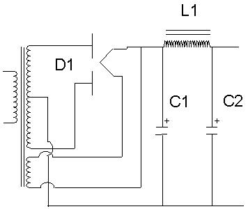
All of the above information is also very useful, in fact exactly the same as for solid state rectifiers. See the schematic below:

As can be plainly seen the only difference is the rectifier. OK, so there are a couple of capacitors and resistors too. But let me 'splain! The resistors are there to reduce high frequency transients and as current limiters. The capacitors across the diodes are to reduce the reverse current switching. SS diodes switch off fast. This creates a spike. The caps reduce the size of the spike. They are generally about 0.1 µF, 1000 volts or better. The voltage level is because when the AC wave on the other side of the diode goes negative, it adds to the positive voltage stored in the capacitor across the diode. So if the filter cap has 350 volts, then the diode can see upwards of over 700 volts across it. The filter choke takes care of it the rest of the way. In fact, the spike is of a far greater frequency than the 120 hertz ripple, so it does a much better job of removing the so-called solid state hash that so many complain about. So, if they merely use a choke, it will be gone and so shoud one of the biggest complaints about SS rectifiers. Hmmm (no, not hummmm). Let's prove this by math:
A 3 henry choke at 120 hertz has a reactance of about 2300 ohms. The same choke at 10 to 20 kilohertz, the region where hash likely is, will have a reactance of:
Xc=2PiFL=6.28x10 000x3=188400
A whopping 188 Kilohms! How the heck can hash get past that! So, a solid state rectifier can be as good if not better, due to its not dropping as much voltage hence not losing that extra power, than a tube rectifier.
Again, the choice is a personal one.
But remember, a steady clean DC is our utimate goal. Our great sounding
undistorted purist amplifier depends on it.
Back Home
Back to Projects
page