I found this baby while browsing about at an antique center. There is an area there that specializes in antique radios but the guy there wants too much for his stuff. But this piece was in another area. It was severely water damaged. It seemed to be calling out to me to save it. So I did. It cost $20 U.S.
At first I was going to bring it to my furniture restorer friend, but I thought I could do it myself. I did.
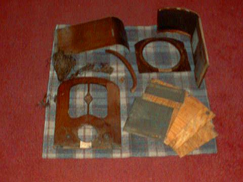
Here is what it looked like before. I took the pieces apart. They almost literally fell apart in my hands.
On the top of the picture are the top and sides. The top is a 2 or 3 millimeter thick piece of veneer. It was cracked and broken in four places. The bottom of the sides were coming apart. It is made of 3/8 inch plywood. The face was dull and the bottom part was also coming apart. The bottom board, at the lower right (yup, those five pieces) literally fell apart into its individual ply layers. It is garbage now. I had to make a new one from 1/2 inch plywood. I used oak, of course. The bracket in the middle for the top is at least still intact. The grill cloth? What a joke!
A gentleman at another site has one of these models. He claims that the veneer is of birdseye maple. This particular radio though looks as though the veneer is oak or mahogany. I chose mahogany. Besides, birdseye maple is three to four times more expensive. Actually, the center triangle piece looks like it is birdseye maple.
This radio has four tubes. They are a 6A7 (aha! Shall I try it in my RCA?), a 6F7, a 42, and an 80. When I first saw the four tubes I thought that it might be a TRF circuit until I saw the label. It is a superhet. The 6F7 tube is actually two tubes in one, a pentode and a triode. So this is a five tube radio! Pentagrid converter, IF amp, detector/triode, power amp and rectifier. My trusty RCA tube manual showed me the error of my ways.
The underside of the chassis looks clean (from being under water?). All of the caps I am going to replace with modern ones. The power supply filter caps are two in one block (literally. It looks like a block of cheddar cheese). I replaced it with two separate filter caps 1/10th the size.
I received the schematic for this model about two weeks after I started working on it. It reveals a few interesting things. For one, the so called "True tone" is nothing that I could see. The schematic reveals no particular bass enhancement whatever. The true tone might be in the speaker. The volume control controls the signal coming in fromthe antenna, so there is no tone contouring done there. However, if there is some kind of level controlled tone it might be done this way:
At the same time as controlling the antenna input, the volume controls the cathode resistor of the 6A7 "heptode" converter. What this does is make the bypass capacitor's reactance cut off at a lower frequency. For example, with the volume setting at maximum, the cathode resistance is 330 ohms, with the bypass cap being 0.1 microfarad. As the volume control is rotated for lower volume, the cathode resistance gets higher. When this happens, the capacitive reactance causes the frequency where it rolls off (audio) to get lower. This seems to imply what I believe that they saw: an AM signal as not only a radio frequency EM but an audio frequency EM as well. Changing the resistance also increases the voltage drop across the resistor, making for a variable bias on the tube. So the amplification of the tube also decreases.
In my opinion, the reason we can't hear the audio riding on an RF AM signal is because the top and bottom part of modulated AM is 180 degrees out of phase. We rectify it to get the positive or negative portion only. At any rate, that is what I can see from the schematic.
It has been totally recapped. The speaker has been replaced with a modern 8 inch from Radio Shack. It sounds really good. I rebuilt and veneered the cabinet and put in the grillecloth I got from Grillecloth. I had to mount the original speakers field coil since it is also a voltage divider supply for grid bias of the 42 output tube and hum filter. I also had to rebuild the oscillator coil and the first IF transformer. The coil and caps were in bad shape. I reconnected the coil and replaced the caps with one I had in a junk box. The oscillator coil needed to be rewound. Here is the procedure I followed:
I found that the oscillator coil was bad. Both rust and someones blade cut though the coils (primary and secondary). So I carefully peeled off the old wiring an counted the windings as I unraveled it. This was no easy task to be sure, as the wire was very thin and broke easily. But before I did this I drew a picture of it and a schematic representation that showed both which coil was connected to which lugs, and the orientation of the windings. The primary of the coil was wound on top of the secondary, and the primary was wound counterclockwise, while the secondary was wound clockwise. I suspect that this was to reduce capacitance. I rewound the coil as the original with the exception of using thicker wire. Unfortunately this caused the inductance to decrease. This can be deduced by this formula:
L=N^2Auu0/l
Where:
L = inductance
N = number of turns
A = cross sectional area of coil form (inner diameter)
u = permeability of core (air = 1, iron = 1000-5000)
u0 = absolute permeability (1.26 x 10^-8)
l = length of coil
As can be easily deduced, the length of the coil, being the denominator, when larger causes the resulting number to be smaller. As a side note you can also see why iron core slugs are used in later radios. It was cheaper to make a coil with less copper wire using an iron core to raise inductance, being that this number was in the numerator.
In any event, after having done this I still got nothing. I then thought that the first IF coil was bad. I did find that the trimmer capacitor was rusted, so having another one in my junk box I replaced that. I also found that one of the windings there was open so I repaired that. I then looked at the second IF coil and found that it was also open. Fortunately for me, each of these breaks were easily repairable. Once I resoldered these and reinstalled them lo and behold the thing actually worked! After making sure that the IF's were tuned to 455 kHz, I then started to try and align the stations with the dial.
As it turns out, I got stations, but the above mentioned change in inductance caused the dial to shift up in frequencies. I had to shunt about 70 (two 47's in series in parallel with one 47) picofarads across the secondary to get some of the stations close to their frequencies. The low end stations are aligned, where the higher stations are off up to about 100kHz. In other words, a station at 1310 kHz is now at about 1450 kHz.
Needless to say, I will need to take apart the oscillator coil again and rewind it with an overall shorter length. To do this I may need to Pi wind it. This makes a little difference in the relationship between length and number of turns etc., but I think it will work.
Well, I did the pi winding several different ways. I first used the same number of turns and it had the same result. Odd, I thought. I then thought that perhaps there was 1) less capacitance due to a thicker gauge and 2) less internal resistance for the same reason. I then tried to use double the turns, or 140 turns Pi wound (multilayer). This caused the thing to over oscillate, if that makes any sense. In other words, every station whistled. I took the thing apart one last time and decided, Ok darn it, I am going to put 50% more turns (110) on one single layer. The coil barely fit the form, but I did it. I also used the original number of turns for the primary (I had used more the second time) thinking that there was too much excitement going on there, and too much capacitance. This time I was succesful. Most of the stations came in on the mark and I got the full range of stations, from below 530 (the dial only goes to 550, but who cares. After 600 the stations come in on the mark) up to 1710. The dial does go up to 1710. This bugger is plenty sensitive. Well, with a 50 foot antenna it is anyway. A couple of folks on other sites claim that the 6A7 converter is bad, but this seems to not be the case with this radio. I wonder if my new oscillator coil made the difference? I was able to improve the reception on an FM radio I had by using a thicker wire for one of the coils that broke. Higher Q? Likely.
Because I needed to adjust the capacitors too extremely, I decided to remove 12 windings from the oscillator coil. I should have only done ten according to my calculations, but my hard head said, no, take two more off just in case so you don't have to take it out again. Lazy fool! Learn from my experience. It is easier to take away than to add. Take away little by little. I knew this but I was being lazy. Well, the idea worked anyway. Now all of the stations are on the money, but with the (fortunately for me the oscillator tuning section had two trimmer caps) trimmers fully closed. But, what counts is that it works. It would have been better with the extra two windings, because I would have had a bit more flexibility with the trimers. But it still works ok.
I used the formula above to find the original value for the oscillator primary. It came out to be 899 microhenries (I know, it seems a bit high, but...) The one I did was about 1200 microhenries. I found that by removing exactly ten windings (and compensating for length) I came up with 900 microhenries. As you can plainly see that is what I should have done. Live and learn.
I also repaired the original power switch. It was riveted together but I managed to pry it apart gently. The switch was merely dirty. Using a 300 grit sand paper I cleaned the contacts and put the unit back together using 12 gauge solid wire to hold it together. It works beautifully.
Here is a picture of the finished product in operation:
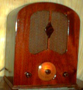
I think it looks pretty good for a
first time major restoration project. I certainly am no carpenter! The
last things I need to do is varnish the bottom trim and glue it to the
cabinet and polish the metalwork (chassis etc). But I may leave well enough
alone.