This circuit is a variation of some I have seen on the net. I use a zener diode and some standard diodes and a darlington connected transistor pair for regulation and hum elimination. This is the difference. It will provide about any voltage level from 2.5 to 12 volts at up to 3 amps of current for your five tube 201a radios. The circuit employs a 12.5 volt center tap (12.5-0-12.5) transformer, though any volt 3 or better amp filament transformer without the center tap will work fine also. I used an NPN small signal transistor with a beta of at least 200. I then use a power transistor that can handle at least 50 watts. I use a bridge rectifier and two silicon diodes that will be used in series with the zener to provide the extra 1.2 volt drop to compensate for the base-emitter junction drops from the two transistors. This way output voltage will be closest to the zener rating. IN my application I needed a 6.3 volt zener, so the emitter of the power transistor should therefore put out +6.3 volts.
One could also use a single darlington transistor instead of two separate transistors. Make sure the beta is 5,000 or more.
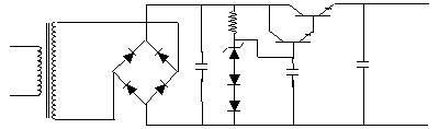
Here is the schematic:
The capacitor on the left is a 470 microfarad 35 volt job. The resistor is 1K. The capacitor from the base of the first transistor (the small signal one) is 47 microfarad. This one virtually eliminated the hum to inaudibility from the horn or earphone or cone speaker in my antique 5 tube radio application. It also clears up the signal because now it is not riding on a 120 cycle hum. The third cap is another 470 microfarad. Of course, the capacitors are electrolytic and the positive terminals are all on top. The positive of the output is also on top, from the emitter, and the negative is the bottom.
The beauty of this circuit is that all you need for heat sinking is the small tab type heat sinks, instead of the large cumbersome ones called for using the 7805 voltage regulator IC for handling the 1.5 amps needed for the 201As (actually about 1.25 amps, 5 x .25 amps. The 7805 is rated for 1 amp). This circuit will be able to handle the units using up to eight 5 volt filament tubes, provided they are no more than .4 amps each, or the total of 3 amps.
I use a darlington pair because the
more current that is drained, the more base current flows. This causes
the resistor to act as a current limiter. The second transistor (actually,
the first in this pair) lowers the current feedback so as to provide less
current limiting while maintaining voltage regulation.
A "B", and "C" BATTERY ELIMINATOR
Coming soon.